
- Pep Smart I/O User's Manual
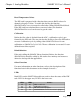
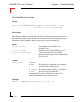
Table Of Contents
- Preface.pdf
- Introduction.pdf
- Table of Contents
- General Information
- Weights & Measures
- 1.1 Product Overview
- 1.2 Ordering Information
- 1.3 Product Information
- 1.4 Installation
- 1.4.1 Overview
- 1.4.2 SMART I/O Module Installation
- 1.4.3 RJ45 Telephone Connector Installation
- 1.4.4 Screw Terminal Block Installation
- 1.4.5 Battery Installation
- 1.5 ISaGRAF-Installation
- 1.5.1 Before Installing
- 1.5.2 Installation of the ISaGRAF for Windows Workbench
- 1.5.3 Installation of PEP Library Functions
- 1.5.4 Demo Application
- Table of Contents
- SM-BASE.pdf
- Table of Contents
- 2. SMART-BASE
- 2.1 Specifications
- 2.2 Board Overview
- 2.3 Functional Description
- 2.4 Configuration
- 2.4.1 Jumper J1: Boot Selection (Pin Connector)
- 2.4.2 Jumper J6: LED Function (Pin Connector)
- 2.5 Pinouts
- 2.5.1 SMART Module Piggyback Connectors
- 2.5.2 Screw Terminal Pinouts
- 2.5.3 Timer I/O Screw Terminal (SCR1)
- 2.5.4 Supply Screw Terminals (SCR2)
- 2.5.5 RS232 Telephone Connector (BU1)
- 2.5.6 RS485 D-Sub Connector for Half-Duplex Operation (Profibus)
- 2.5.7 SPI Connector (ST7)
- 2.6 ‘C’ Programming
- 2.6.1 SMART-BASE Library
- 2.6.2 SMTselIn
- 2.6.3 SMTsettout
- 2.6.4 SMTpre
- 2.6.5 SMTstasto
- 2.6.6 SMTrd
- 2.6.7 SMTtin
- 2.6.8 SMTstat
- 2.6.9 SMTout
- 2.6.10 SMLed
- 2.6.11 SMwdon
- 2.6.12 SMwdtrig
- 2.6.13 SMwdoff
- 2.7 ISaGRAF Programming
- 2.7.1 The ISaGRAF Board Parameters
- 2.7.2 The ISaGRAF Operate Calls
- 2.8 Flash Utility
- Table of Contents
- SM-EXT.pdf
- Digital.pdf
- Table of Contents
- 4. Digital Modules
- 4.1 SM-DIN1
- 4.1.1 Introduction
- 4.1.2 Specifications
- 4.1.3 Front Panel Layout
- 4.1.4 Board Overview
- 4.1.5 Functional Description
- 4.1.6 Configuration
- 4.1.7 Pinouts
- 4.1.8 ‘C’ Programming
- 4.1.8.1 SM-DIN1 Library
- 4.1.8.2 SMDIN1Init
- 4.1.8.3 SMDIN1DeInit
- 4.1.8.4 SMDIN1Get
- 4.1.9 ISaGRAF Programming
- 4.1.9.1 The ISaGRAF Board Parameters
- 4.1.9.2 The ISaGRAF Operate Calls
- 4.2 SM-DOUT1
- 4.2.1 Introduction
- 4.2.2 Specifications
- 4.2.3 Front Panel Layout
- 4.2.4 Board Overview
- 4.2.5 Functional Description
- 4.2.6 Configuration
- 4.2.7 Pinouts
- 4.2.8 ‘C’ Programming
- 4.2.8.1 SM-DOUT1 Library
- 4.2.8.2 SMDOUT1Init
- 4.2.8.3 SMDOUT1DeInit
- 4.2.8.4 SMDOUT1Get
- 4.2.8.5 SMDOUT1Set
- 4.2.9 ISaGRAF Programming
- 4.2.9.1 The ISaGRAF Board Parameters
- 4.2.9.2 The ISaGRAF Operate Calls
- 4.3 SM-REL1
- 4.3.1 Introduction
- 4.3.2 Specifications
- 4.3.3 Front Panel Layout
- 4.3.4 Board Overview
- 4.3.5 Functional Description
- 4.3.6 Configuration
- 4.3.7 Pinouts
- 4.3.8 ‘C’ Programming
- 4.3.8.1 SM-REL1 Library
- 4.3.8.2 SMREL1Init
- 4.3.8.3 SMREL1DeInit
- 4.3.8.4 SMREL1Reset
- 4.3.8.5 SMREL1GetRly
- 4.3.8.6 SMREL1SetRly
- 4.3.8.7 SMREL1GetLed
- 4.3.8.8 SMREL1SetLed
- 4.3.8.9 SMREL1GetExtVcc
- 4.3.9 ISaGRAF Programming
- 4.3.9.1 The ISaGRAF Board Parameters
- 4.3.9.2 The ISaGRAF Operate Calls
- Table of Contents
- Analog.pdf
- Table of Contents
- 5. Analog Modules
- 5.1 SM-DAD1
- 5.1.1 Introduction
- 5.1.2 Specifications
- 5.1.3 Front Panel Layout
- 5.1.4 Board Overview
- 5.1.5 Functional Description
- 5.1.5.1 Input Circuitry
- 5.1.5.2 Output Circuitry
- 5.1.6 Configuration
- 5.1.7 Pinouts
- 5.1.8 ‘C’ Programming
- 5.1.8.1 SM-DAD1 Library
- 5.1.8.2 SMDAD1Init
- 5.1.8.3 SMDAD1DeInit
- 5.1.8.4 SMDAD1GetVRaw
- 5.1.8.5 SMDAD1GetV
- 5.1.8.6 SMDAD1PutVRaw
- 5.1.8.7 SMDAD1PutV
- 5.1.8.8 SMDAD1SetLed
- 5.1.8.9 SMDAD1ClrLed
- 5.1.9 ISaGRAF Programming
- 5.1.9.1 The ISaGRAF Board Parameters
- 5.1.9.2 The ISaGRAF Operate Calls
- 5.2 SM-PT100
- 5.2.1 Introduction
- 5.2.2 Specifications
- 5.2.3 Front Panel Layout
- 5.2.4 Board Overview
- 5.2.5 Functional Description
- 5.2.6 Configuration
- 5.2.7 Pinouts
- 5.2.8 ‘C’ Programming
- 5.2.8.1 SM-PT100 Library
- 5.2.8.2 SMADCInit
- 5.2.8.3 SMADCCalibrate
- 5.2.8.4 SMADCSetCyclicCalib
- 5.2.8.5 SMADCSetSensorType
- 5.2.8.6 SMADCGetSensorType
- 5.2.8.7 SMADCSetPrecision
- 5.2.8.8 SMADCGetPrecision
- 5.2.8.9 SMADCSetMode
- 5.2.8.10 SMADCGetMode 5-47
- 5.2.8.11 SMADCSetSignal
- 5.2.8.12 SMADCSetGain
- 5.2.8.13 SMADCGetGain
- 5.2.8.14 SMADCEnableRead
- 5.2.8.15 SMADCEnableConversion
- 5.2.8.16 SMADCReadRaw
- 5.2.8.17 SMADCReadConverted
- 5.2.8.18 SMADCDeinit
- 5.2.9 ISaGRAF Programming
- 5.2.9.1 The ISaGRAF Board Parameters
- 5.2.9.2 The ISaGRAF Operate Calls
- 5.3 SM-THERM
- 5.3.1 Introduction
- 5.3.2 Specifications
- 5.3.3 Front Panel Layout
- 5.3.4 Board Overview
- 5.3.5 Functional Description
- 5.3.6 Configuration
- 5.3.7 Pinouts
- 5.3.8 ‘C’ Programming
- 5.3.8.1 SM-THERM Library
- 5.3.8.2 SMADCInit
- 5.3.8.3 SMADCCalibrate
- 5.3.8.4 SMADCSetCyclicCalib
- 5.3.8.5 SMADCSetSensorType
- 5.3.8.6 SMADCGetSensorType
- 5.3.8.7 SMADCSetPrecision
- 5.3.8.8 SMADCGetPrecision
- 5.3.8.9 SMADCSetMode 5-75
- 5.3.8.10 SMADCGetMode
- 5.3.8.11 SMADCSetSignal
- 5.3.8.12 SMADCSetGain
- 5.3.8.13 SMADCGetGain
- 5.3.8.14 SMADCEnableRead
- 5.3.8.15 SMADCEnableConversion
- 5.3.8.16 SMADCReadRaw
- 5.3.8.17 SMADCReadConverted
- 5.3.8.18 SMADCDeinit
- 5.3.9 ISaGRAF Programming
- 5.3.9.1 The ISaGRAF Board Parameters
- 5.3.9.2 The ISaGRAF Operate Calls
- 5.4 SM-ADC1
- 5.4.1 Introduction
- 5.4.2 Specifications
- 5.4.3 Front Panel Layout
- 5.4.4 Board Overview
- 5.4.5 Functional Description
- 5.4.5.1 Input Circuitry
- 5.4.6 Configuration
- 5.4.7 Pinouts
- 5.4.8 ‘C’ Programming
- 5.4.8.1 SM-ADC1 Library
- 5.4.8.2 SMADC1Init
- 5.4.8.3 SMADC1GetVRaw
- 5.4.8.4 SMADC1GetV
- 5.4.8.5 SMADC1SetLed
- 5.4.8.6 SMADC1ClrLed
- 5.4.8.7 SMADC1DeInit
- 5.4.9 ISaGRAF Programming
- 5.4.9.1 The ISaGRAF Board Parameters
- 5.4.9.2 The ISaGRAF Operate Calls
- 5.5 SM-DAC1
- 5.5.1 Introduction
- 5.5.2 Specifications
- 5.5.3 Front Panel Layout
- 5.5.4 Board Overview
- 5.5.5 Functional Description
- 5.5.5.1 Output Circuitry
- 5.5.6 Configuration
- 5.5.7 Pinouts
- 5.5.8 ‘C’ Programming
- 5.5.8.1 SM-DAC1 Library
- 5.5.8.2 SMDAC1Init
- 5.5.8.3 SMDAC1OpenLoop
- 5.5.8.4 SMADAC1Operate
- 5.5.8.5 SMDAC1StandBy
- 5.5.8.6 SMDAC1PutVRaw
- 5.5.8.7 SMDAC1PutV
- 5.5.8.8 SMDAC1SetLed
- 5.5.8.9 SMDAC1ClrLed
- 5.5.8.10 SMDAC1DeInit
- 5.5.9 ISaGRAF Programming
- 5.5.9.1 The ISaGRAF Board Parameters
- 5.5.9.2 The ISaGRAF Operate Calls
- Table of Contents
- Comms.pdf
- Table of Contents
- 6. Communications Modules
- 6.1 SM-RS232 6
- 6.1.1 Introduction
- 6.1.2 Specifications
- 6.1.3 Front Panel Layout
- 6.1.4 Board Overview
- 6.1.5 Functional Description
- 6.1.6 Configuration
- 6.1.7 Pinouts
- 6.1.8 ISaGRAF Programming
- 6.1.8.1 The ISaGRAF Board Parameters
- 6.1.8.2 The ISaGRAF Operate Calls
- 6.1.9 OS-9 Programming
- 6.2 SM-SSI
- 6.2.1 Introduction
- 6.2.2 Specifications
- 6.2.3 Front Panel Layout
- 6.2.4 Board Overview
- 6.2.5 Functional Description
- 6.2.6 SSI Operation
- 6.2.7 Register Description
- 6.2.7.1 Control Register
- 6.2.7.2 CTRL1 Register
- 6.2.7.3 CTRL2 Register
- 6.2.7.4 CTRL3 Register
- 6.2.7.5 Compare Register
- 6.2.7.6 Identification Register
- 6.2.7.7 Status Register
- 6.2.7.8 STAT1 Register
- 6.2.7.9 STAT2 Register
- 6.2.7.10 Data Register
- 6.2.8 MATCH Function
- 6.2.9 Tested Sensors
- 6.2.10 Configuration
- 6.2.11 Pinouts
- 6.2.12 ‘C’ Programming
- 6.2.12.1 SM-SSI Library
- 6.2.12.2 SMSSIInit
- 6.2.12.3 SMSSIDeInit
- 6.2.12.4 SMSSISetSetPoint
- 6.2.12.5 SMSSISetCtrlReg
- 6.2.12.6 SMSSIGetStatus
- 6.2.12.7 SMSSIGetData
- 6.2.13 ISaGRAF Programming
- 6.2.13.1 The ISaGRAF Board Parameters
- Table of Contents
SMART I/O User’s Manual
©1996 PEP Modular Computers GmbHMarch 12, 1996 Page 5 - 37
5
Chapter 5 Analog Modules
Read Temperature Values
The HW task is prepared with a function that converts RAW values of a
channel to degrees Celsius. To enable this facility, the function
SMADCEnableConversion must be called after calling SMADCEnableRead.
If the HW task has calculated these converted values, the function
SMADCReadConverted can be used to get the value.
Calibration
Before the first value is fetched from the ADC, a calibration cycle is per-
formed by the HW task. The user also has the facility to force the HW task to
execute a calibration cycle by calling either SMADCCalibrate for one
calibration or SMADCSetCyclicCalib. Then a calibration is executed if a user
defined interval has expired.
Deinitialization:
If the task calling the SMADC library function finishes, the function
SMADCDeInit should be called by this task to free memory and resources
otherwise tied up with the application.
Other Functions
For more information on other functions, refer to the description of the
functions later in this document or the example demoadc.c.
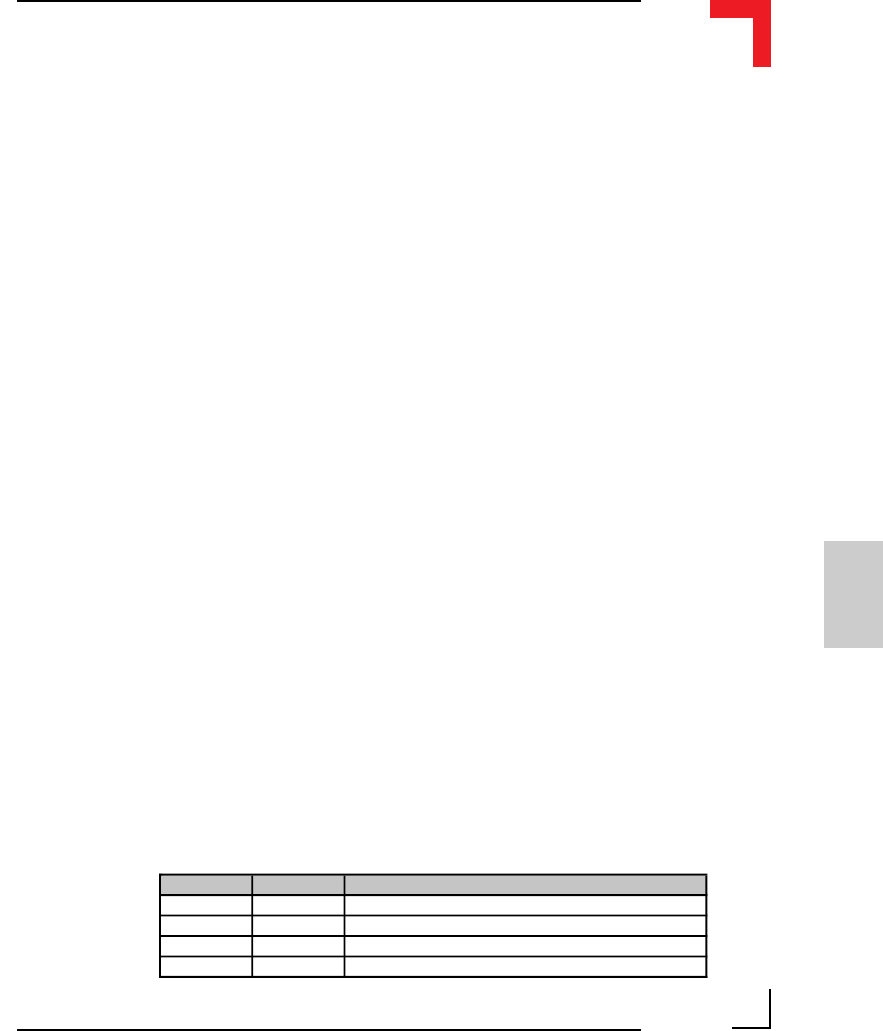
LEDs
Both LEDs on the SM-PT100 module are used to show the status of the HW
task. LED1 is the upper one; LED2 is the lower one.
LED1 LED2 Status
off off ADC is not in use
on off Calibration in progress
off on AD conversion in progress
on on Standardization to reference value in progress