
- Pep Smart I/O User's Manual
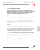
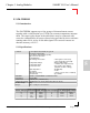
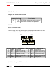
Table Of Contents
- Preface.pdf
- Introduction.pdf
- Table of Contents
- General Information
- Weights & Measures
- 1.1 Product Overview
- 1.2 Ordering Information
- 1.3 Product Information
- 1.4 Installation
- 1.4.1 Overview
- 1.4.2 SMART I/O Module Installation
- 1.4.3 RJ45 Telephone Connector Installation
- 1.4.4 Screw Terminal Block Installation
- 1.4.5 Battery Installation
- 1.5 ISaGRAF-Installation
- 1.5.1 Before Installing
- 1.5.2 Installation of the ISaGRAF for Windows Workbench
- 1.5.3 Installation of PEP Library Functions
- 1.5.4 Demo Application
- Table of Contents
- SM-BASE.pdf
- Table of Contents
- 2. SMART-BASE
- 2.1 Specifications
- 2.2 Board Overview
- 2.3 Functional Description
- 2.4 Configuration
- 2.4.1 Jumper J1: Boot Selection (Pin Connector)
- 2.4.2 Jumper J6: LED Function (Pin Connector)
- 2.5 Pinouts
- 2.5.1 SMART Module Piggyback Connectors
- 2.5.2 Screw Terminal Pinouts
- 2.5.3 Timer I/O Screw Terminal (SCR1)
- 2.5.4 Supply Screw Terminals (SCR2)
- 2.5.5 RS232 Telephone Connector (BU1)
- 2.5.6 RS485 D-Sub Connector for Half-Duplex Operation (Profibus)
- 2.5.7 SPI Connector (ST7)
- 2.6 ‘C’ Programming
- 2.6.1 SMART-BASE Library
- 2.6.2 SMTselIn
- 2.6.3 SMTsettout
- 2.6.4 SMTpre
- 2.6.5 SMTstasto
- 2.6.6 SMTrd
- 2.6.7 SMTtin
- 2.6.8 SMTstat
- 2.6.9 SMTout
- 2.6.10 SMLed
- 2.6.11 SMwdon
- 2.6.12 SMwdtrig
- 2.6.13 SMwdoff
- 2.7 ISaGRAF Programming
- 2.7.1 The ISaGRAF Board Parameters
- 2.7.2 The ISaGRAF Operate Calls
- 2.8 Flash Utility
- Table of Contents
- SM-EXT.pdf
- Digital.pdf
- Table of Contents
- 4. Digital Modules
- 4.1 SM-DIN1
- 4.1.1 Introduction
- 4.1.2 Specifications
- 4.1.3 Front Panel Layout
- 4.1.4 Board Overview
- 4.1.5 Functional Description
- 4.1.6 Configuration
- 4.1.7 Pinouts
- 4.1.8 ‘C’ Programming
- 4.1.8.1 SM-DIN1 Library
- 4.1.8.2 SMDIN1Init
- 4.1.8.3 SMDIN1DeInit
- 4.1.8.4 SMDIN1Get
- 4.1.9 ISaGRAF Programming
- 4.1.9.1 The ISaGRAF Board Parameters
- 4.1.9.2 The ISaGRAF Operate Calls
- 4.2 SM-DOUT1
- 4.2.1 Introduction
- 4.2.2 Specifications
- 4.2.3 Front Panel Layout
- 4.2.4 Board Overview
- 4.2.5 Functional Description
- 4.2.6 Configuration
- 4.2.7 Pinouts
- 4.2.8 ‘C’ Programming
- 4.2.8.1 SM-DOUT1 Library
- 4.2.8.2 SMDOUT1Init
- 4.2.8.3 SMDOUT1DeInit
- 4.2.8.4 SMDOUT1Get
- 4.2.8.5 SMDOUT1Set
- 4.2.9 ISaGRAF Programming
- 4.2.9.1 The ISaGRAF Board Parameters
- 4.2.9.2 The ISaGRAF Operate Calls
- 4.3 SM-REL1
- 4.3.1 Introduction
- 4.3.2 Specifications
- 4.3.3 Front Panel Layout
- 4.3.4 Board Overview
- 4.3.5 Functional Description
- 4.3.6 Configuration
- 4.3.7 Pinouts
- 4.3.8 ‘C’ Programming
- 4.3.8.1 SM-REL1 Library
- 4.3.8.2 SMREL1Init
- 4.3.8.3 SMREL1DeInit
- 4.3.8.4 SMREL1Reset
- 4.3.8.5 SMREL1GetRly
- 4.3.8.6 SMREL1SetRly
- 4.3.8.7 SMREL1GetLed
- 4.3.8.8 SMREL1SetLed
- 4.3.8.9 SMREL1GetExtVcc
- 4.3.9 ISaGRAF Programming
- 4.3.9.1 The ISaGRAF Board Parameters
- 4.3.9.2 The ISaGRAF Operate Calls
- Table of Contents
- Analog.pdf
- Table of Contents
- 5. Analog Modules
- 5.1 SM-DAD1
- 5.1.1 Introduction
- 5.1.2 Specifications
- 5.1.3 Front Panel Layout
- 5.1.4 Board Overview
- 5.1.5 Functional Description
- 5.1.5.1 Input Circuitry
- 5.1.5.2 Output Circuitry
- 5.1.6 Configuration
- 5.1.7 Pinouts
- 5.1.8 ‘C’ Programming
- 5.1.8.1 SM-DAD1 Library
- 5.1.8.2 SMDAD1Init
- 5.1.8.3 SMDAD1DeInit
- 5.1.8.4 SMDAD1GetVRaw
- 5.1.8.5 SMDAD1GetV
- 5.1.8.6 SMDAD1PutVRaw
- 5.1.8.7 SMDAD1PutV
- 5.1.8.8 SMDAD1SetLed
- 5.1.8.9 SMDAD1ClrLed
- 5.1.9 ISaGRAF Programming
- 5.1.9.1 The ISaGRAF Board Parameters
- 5.1.9.2 The ISaGRAF Operate Calls
- 5.2 SM-PT100
- 5.2.1 Introduction
- 5.2.2 Specifications
- 5.2.3 Front Panel Layout
- 5.2.4 Board Overview
- 5.2.5 Functional Description
- 5.2.6 Configuration
- 5.2.7 Pinouts
- 5.2.8 ‘C’ Programming
- 5.2.8.1 SM-PT100 Library
- 5.2.8.2 SMADCInit
- 5.2.8.3 SMADCCalibrate
- 5.2.8.4 SMADCSetCyclicCalib
- 5.2.8.5 SMADCSetSensorType
- 5.2.8.6 SMADCGetSensorType
- 5.2.8.7 SMADCSetPrecision
- 5.2.8.8 SMADCGetPrecision
- 5.2.8.9 SMADCSetMode
- 5.2.8.10 SMADCGetMode 5-47
- 5.2.8.11 SMADCSetSignal
- 5.2.8.12 SMADCSetGain
- 5.2.8.13 SMADCGetGain
- 5.2.8.14 SMADCEnableRead
- 5.2.8.15 SMADCEnableConversion
- 5.2.8.16 SMADCReadRaw
- 5.2.8.17 SMADCReadConverted
- 5.2.8.18 SMADCDeinit
- 5.2.9 ISaGRAF Programming
- 5.2.9.1 The ISaGRAF Board Parameters
- 5.2.9.2 The ISaGRAF Operate Calls
- 5.3 SM-THERM
- 5.3.1 Introduction
- 5.3.2 Specifications
- 5.3.3 Front Panel Layout
- 5.3.4 Board Overview
- 5.3.5 Functional Description
- 5.3.6 Configuration
- 5.3.7 Pinouts
- 5.3.8 ‘C’ Programming
- 5.3.8.1 SM-THERM Library
- 5.3.8.2 SMADCInit
- 5.3.8.3 SMADCCalibrate
- 5.3.8.4 SMADCSetCyclicCalib
- 5.3.8.5 SMADCSetSensorType
- 5.3.8.6 SMADCGetSensorType
- 5.3.8.7 SMADCSetPrecision
- 5.3.8.8 SMADCGetPrecision
- 5.3.8.9 SMADCSetMode 5-75
- 5.3.8.10 SMADCGetMode
- 5.3.8.11 SMADCSetSignal
- 5.3.8.12 SMADCSetGain
- 5.3.8.13 SMADCGetGain
- 5.3.8.14 SMADCEnableRead
- 5.3.8.15 SMADCEnableConversion
- 5.3.8.16 SMADCReadRaw
- 5.3.8.17 SMADCReadConverted
- 5.3.8.18 SMADCDeinit
- 5.3.9 ISaGRAF Programming
- 5.3.9.1 The ISaGRAF Board Parameters
- 5.3.9.2 The ISaGRAF Operate Calls
- 5.4 SM-ADC1
- 5.4.1 Introduction
- 5.4.2 Specifications
- 5.4.3 Front Panel Layout
- 5.4.4 Board Overview
- 5.4.5 Functional Description
- 5.4.5.1 Input Circuitry
- 5.4.6 Configuration
- 5.4.7 Pinouts
- 5.4.8 ‘C’ Programming
- 5.4.8.1 SM-ADC1 Library
- 5.4.8.2 SMADC1Init
- 5.4.8.3 SMADC1GetVRaw
- 5.4.8.4 SMADC1GetV
- 5.4.8.5 SMADC1SetLed
- 5.4.8.6 SMADC1ClrLed
- 5.4.8.7 SMADC1DeInit
- 5.4.9 ISaGRAF Programming
- 5.4.9.1 The ISaGRAF Board Parameters
- 5.4.9.2 The ISaGRAF Operate Calls
- 5.5 SM-DAC1
- 5.5.1 Introduction
- 5.5.2 Specifications
- 5.5.3 Front Panel Layout
- 5.5.4 Board Overview
- 5.5.5 Functional Description
- 5.5.5.1 Output Circuitry
- 5.5.6 Configuration
- 5.5.7 Pinouts
- 5.5.8 ‘C’ Programming
- 5.5.8.1 SM-DAC1 Library
- 5.5.8.2 SMDAC1Init
- 5.5.8.3 SMDAC1OpenLoop
- 5.5.8.4 SMADAC1Operate
- 5.5.8.5 SMDAC1StandBy
- 5.5.8.6 SMDAC1PutVRaw
- 5.5.8.7 SMDAC1PutV
- 5.5.8.8 SMDAC1SetLed
- 5.5.8.9 SMDAC1ClrLed
- 5.5.8.10 SMDAC1DeInit
- 5.5.9 ISaGRAF Programming
- 5.5.9.1 The ISaGRAF Board Parameters
- 5.5.9.2 The ISaGRAF Operate Calls
- Table of Contents
- Comms.pdf
- Table of Contents
- 6. Communications Modules
- 6.1 SM-RS232 6
- 6.1.1 Introduction
- 6.1.2 Specifications
- 6.1.3 Front Panel Layout
- 6.1.4 Board Overview
- 6.1.5 Functional Description
- 6.1.6 Configuration
- 6.1.7 Pinouts
- 6.1.8 ISaGRAF Programming
- 6.1.8.1 The ISaGRAF Board Parameters
- 6.1.8.2 The ISaGRAF Operate Calls
- 6.1.9 OS-9 Programming
- 6.2 SM-SSI
- 6.2.1 Introduction
- 6.2.2 Specifications
- 6.2.3 Front Panel Layout
- 6.2.4 Board Overview
- 6.2.5 Functional Description
- 6.2.6 SSI Operation
- 6.2.7 Register Description
- 6.2.7.1 Control Register
- 6.2.7.2 CTRL1 Register
- 6.2.7.3 CTRL2 Register
- 6.2.7.4 CTRL3 Register
- 6.2.7.5 Compare Register
- 6.2.7.6 Identification Register
- 6.2.7.7 Status Register
- 6.2.7.8 STAT1 Register
- 6.2.7.9 STAT2 Register
- 6.2.7.10 Data Register
- 6.2.8 MATCH Function
- 6.2.9 Tested Sensors
- 6.2.10 Configuration
- 6.2.11 Pinouts
- 6.2.12 ‘C’ Programming
- 6.2.12.1 SM-SSI Library
- 6.2.12.2 SMSSIInit
- 6.2.12.3 SMSSIDeInit
- 6.2.12.4 SMSSISetSetPoint
- 6.2.12.5 SMSSISetCtrlReg
- 6.2.12.6 SMSSIGetStatus
- 6.2.12.7 SMSSIGetData
- 6.2.13 ISaGRAF Programming
- 6.2.13.1 The ISaGRAF Board Parameters
- Table of Contents
SMART I/O User’s Manual
March 12, 1996
©1996 PEP Modular Computers GmbH
Page 5 - 56
Chapter 5 Analog Modules
5.2.9 ISaGRAF Programming
5.2.9.1 The ISaGRAF Board Parameters
Information on board parameters may be found in the PEP online help and
ISaGRAF online help or user’s manual.
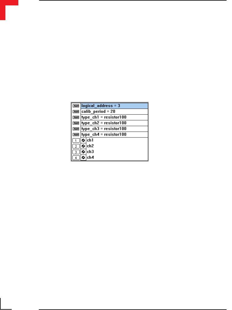
Figure 5.2.9.1.1 a Typical Screen Section for the SM-PT100 Module
Logical Address
The 4 inputs of this module may be clearly seen together with the logical
address at which this particular board is residing. Remember, this logical
address is the same as the physical slot position! In the example shown here,
the board being addressed is in slot 3 i.e. the third of the SMART-BASE
slots. Up to 11 slots are catered for in the SMART I/O concept; 3 on the
SMART-BASE and 2 for each connected SMART-EXT (up to a total of 4).
Module Specific Information :
calib_period : This is the time in seconds for cyclic calibration if
required. An entry of zero disables the function.
type_ch(x) : This parameter is either resistor100 or PT100
depending whether the returned value should be raw
ohmic or calibrated in degrees Celsius respectively.