
- Pep Smart I/O User's Manual
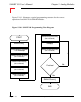
Table Of Contents
- Preface.pdf
- Introduction.pdf
- Table of Contents
- General Information
- Weights & Measures
- 1.1 Product Overview
- 1.2 Ordering Information
- 1.3 Product Information
- 1.4 Installation
- 1.4.1 Overview
- 1.4.2 SMART I/O Module Installation
- 1.4.3 RJ45 Telephone Connector Installation
- 1.4.4 Screw Terminal Block Installation
- 1.4.5 Battery Installation
- 1.5 ISaGRAF-Installation
- 1.5.1 Before Installing
- 1.5.2 Installation of the ISaGRAF for Windows Workbench
- 1.5.3 Installation of PEP Library Functions
- 1.5.4 Demo Application
- Table of Contents
- SM-BASE.pdf
- Table of Contents
- 2. SMART-BASE
- 2.1 Specifications
- 2.2 Board Overview
- 2.3 Functional Description
- 2.4 Configuration
- 2.4.1 Jumper J1: Boot Selection (Pin Connector)
- 2.4.2 Jumper J6: LED Function (Pin Connector)
- 2.5 Pinouts
- 2.5.1 SMART Module Piggyback Connectors
- 2.5.2 Screw Terminal Pinouts
- 2.5.3 Timer I/O Screw Terminal (SCR1)
- 2.5.4 Supply Screw Terminals (SCR2)
- 2.5.5 RS232 Telephone Connector (BU1)
- 2.5.6 RS485 D-Sub Connector for Half-Duplex Operation (Profibus)
- 2.5.7 SPI Connector (ST7)
- 2.6 ‘C’ Programming
- 2.6.1 SMART-BASE Library
- 2.6.2 SMTselIn
- 2.6.3 SMTsettout
- 2.6.4 SMTpre
- 2.6.5 SMTstasto
- 2.6.6 SMTrd
- 2.6.7 SMTtin
- 2.6.8 SMTstat
- 2.6.9 SMTout
- 2.6.10 SMLed
- 2.6.11 SMwdon
- 2.6.12 SMwdtrig
- 2.6.13 SMwdoff
- 2.7 ISaGRAF Programming
- 2.7.1 The ISaGRAF Board Parameters
- 2.7.2 The ISaGRAF Operate Calls
- 2.8 Flash Utility
- Table of Contents
- SM-EXT.pdf
- Digital.pdf
- Table of Contents
- 4. Digital Modules
- 4.1 SM-DIN1
- 4.1.1 Introduction
- 4.1.2 Specifications
- 4.1.3 Front Panel Layout
- 4.1.4 Board Overview
- 4.1.5 Functional Description
- 4.1.6 Configuration
- 4.1.7 Pinouts
- 4.1.8 ‘C’ Programming
- 4.1.8.1 SM-DIN1 Library
- 4.1.8.2 SMDIN1Init
- 4.1.8.3 SMDIN1DeInit
- 4.1.8.4 SMDIN1Get
- 4.1.9 ISaGRAF Programming
- 4.1.9.1 The ISaGRAF Board Parameters
- 4.1.9.2 The ISaGRAF Operate Calls
- 4.2 SM-DOUT1
- 4.2.1 Introduction
- 4.2.2 Specifications
- 4.2.3 Front Panel Layout
- 4.2.4 Board Overview
- 4.2.5 Functional Description
- 4.2.6 Configuration
- 4.2.7 Pinouts
- 4.2.8 ‘C’ Programming
- 4.2.8.1 SM-DOUT1 Library
- 4.2.8.2 SMDOUT1Init
- 4.2.8.3 SMDOUT1DeInit
- 4.2.8.4 SMDOUT1Get
- 4.2.8.5 SMDOUT1Set
- 4.2.9 ISaGRAF Programming
- 4.2.9.1 The ISaGRAF Board Parameters
- 4.2.9.2 The ISaGRAF Operate Calls
- 4.3 SM-REL1
- 4.3.1 Introduction
- 4.3.2 Specifications
- 4.3.3 Front Panel Layout
- 4.3.4 Board Overview
- 4.3.5 Functional Description
- 4.3.6 Configuration
- 4.3.7 Pinouts
- 4.3.8 ‘C’ Programming
- 4.3.8.1 SM-REL1 Library
- 4.3.8.2 SMREL1Init
- 4.3.8.3 SMREL1DeInit
- 4.3.8.4 SMREL1Reset
- 4.3.8.5 SMREL1GetRly
- 4.3.8.6 SMREL1SetRly
- 4.3.8.7 SMREL1GetLed
- 4.3.8.8 SMREL1SetLed
- 4.3.8.9 SMREL1GetExtVcc
- 4.3.9 ISaGRAF Programming
- 4.3.9.1 The ISaGRAF Board Parameters
- 4.3.9.2 The ISaGRAF Operate Calls
- Table of Contents
- Analog.pdf
- Table of Contents
- 5. Analog Modules
- 5.1 SM-DAD1
- 5.1.1 Introduction
- 5.1.2 Specifications
- 5.1.3 Front Panel Layout
- 5.1.4 Board Overview
- 5.1.5 Functional Description
- 5.1.5.1 Input Circuitry
- 5.1.5.2 Output Circuitry
- 5.1.6 Configuration
- 5.1.7 Pinouts
- 5.1.8 ‘C’ Programming
- 5.1.8.1 SM-DAD1 Library
- 5.1.8.2 SMDAD1Init
- 5.1.8.3 SMDAD1DeInit
- 5.1.8.4 SMDAD1GetVRaw
- 5.1.8.5 SMDAD1GetV
- 5.1.8.6 SMDAD1PutVRaw
- 5.1.8.7 SMDAD1PutV
- 5.1.8.8 SMDAD1SetLed
- 5.1.8.9 SMDAD1ClrLed
- 5.1.9 ISaGRAF Programming
- 5.1.9.1 The ISaGRAF Board Parameters
- 5.1.9.2 The ISaGRAF Operate Calls
- 5.2 SM-PT100
- 5.2.1 Introduction
- 5.2.2 Specifications
- 5.2.3 Front Panel Layout
- 5.2.4 Board Overview
- 5.2.5 Functional Description
- 5.2.6 Configuration
- 5.2.7 Pinouts
- 5.2.8 ‘C’ Programming
- 5.2.8.1 SM-PT100 Library
- 5.2.8.2 SMADCInit
- 5.2.8.3 SMADCCalibrate
- 5.2.8.4 SMADCSetCyclicCalib
- 5.2.8.5 SMADCSetSensorType
- 5.2.8.6 SMADCGetSensorType
- 5.2.8.7 SMADCSetPrecision
- 5.2.8.8 SMADCGetPrecision
- 5.2.8.9 SMADCSetMode
- 5.2.8.10 SMADCGetMode 5-47
- 5.2.8.11 SMADCSetSignal
- 5.2.8.12 SMADCSetGain
- 5.2.8.13 SMADCGetGain
- 5.2.8.14 SMADCEnableRead
- 5.2.8.15 SMADCEnableConversion
- 5.2.8.16 SMADCReadRaw
- 5.2.8.17 SMADCReadConverted
- 5.2.8.18 SMADCDeinit
- 5.2.9 ISaGRAF Programming
- 5.2.9.1 The ISaGRAF Board Parameters
- 5.2.9.2 The ISaGRAF Operate Calls
- 5.3 SM-THERM
- 5.3.1 Introduction
- 5.3.2 Specifications
- 5.3.3 Front Panel Layout
- 5.3.4 Board Overview
- 5.3.5 Functional Description
- 5.3.6 Configuration
- 5.3.7 Pinouts
- 5.3.8 ‘C’ Programming
- 5.3.8.1 SM-THERM Library
- 5.3.8.2 SMADCInit
- 5.3.8.3 SMADCCalibrate
- 5.3.8.4 SMADCSetCyclicCalib
- 5.3.8.5 SMADCSetSensorType
- 5.3.8.6 SMADCGetSensorType
- 5.3.8.7 SMADCSetPrecision
- 5.3.8.8 SMADCGetPrecision
- 5.3.8.9 SMADCSetMode 5-75
- 5.3.8.10 SMADCGetMode
- 5.3.8.11 SMADCSetSignal
- 5.3.8.12 SMADCSetGain
- 5.3.8.13 SMADCGetGain
- 5.3.8.14 SMADCEnableRead
- 5.3.8.15 SMADCEnableConversion
- 5.3.8.16 SMADCReadRaw
- 5.3.8.17 SMADCReadConverted
- 5.3.8.18 SMADCDeinit
- 5.3.9 ISaGRAF Programming
- 5.3.9.1 The ISaGRAF Board Parameters
- 5.3.9.2 The ISaGRAF Operate Calls
- 5.4 SM-ADC1
- 5.4.1 Introduction
- 5.4.2 Specifications
- 5.4.3 Front Panel Layout
- 5.4.4 Board Overview
- 5.4.5 Functional Description
- 5.4.5.1 Input Circuitry
- 5.4.6 Configuration
- 5.4.7 Pinouts
- 5.4.8 ‘C’ Programming
- 5.4.8.1 SM-ADC1 Library
- 5.4.8.2 SMADC1Init
- 5.4.8.3 SMADC1GetVRaw
- 5.4.8.4 SMADC1GetV
- 5.4.8.5 SMADC1SetLed
- 5.4.8.6 SMADC1ClrLed
- 5.4.8.7 SMADC1DeInit
- 5.4.9 ISaGRAF Programming
- 5.4.9.1 The ISaGRAF Board Parameters
- 5.4.9.2 The ISaGRAF Operate Calls
- 5.5 SM-DAC1
- 5.5.1 Introduction
- 5.5.2 Specifications
- 5.5.3 Front Panel Layout
- 5.5.4 Board Overview
- 5.5.5 Functional Description
- 5.5.5.1 Output Circuitry
- 5.5.6 Configuration
- 5.5.7 Pinouts
- 5.5.8 ‘C’ Programming
- 5.5.8.1 SM-DAC1 Library
- 5.5.8.2 SMDAC1Init
- 5.5.8.3 SMDAC1OpenLoop
- 5.5.8.4 SMADAC1Operate
- 5.5.8.5 SMDAC1StandBy
- 5.5.8.6 SMDAC1PutVRaw
- 5.5.8.7 SMDAC1PutV
- 5.5.8.8 SMDAC1SetLed
- 5.5.8.9 SMDAC1ClrLed
- 5.5.8.10 SMDAC1DeInit
- 5.5.9 ISaGRAF Programming
- 5.5.9.1 The ISaGRAF Board Parameters
- 5.5.9.2 The ISaGRAF Operate Calls
- Table of Contents
- Comms.pdf
- Table of Contents
- 6. Communications Modules
- 6.1 SM-RS232 6
- 6.1.1 Introduction
- 6.1.2 Specifications
- 6.1.3 Front Panel Layout
- 6.1.4 Board Overview
- 6.1.5 Functional Description
- 6.1.6 Configuration
- 6.1.7 Pinouts
- 6.1.8 ISaGRAF Programming
- 6.1.8.1 The ISaGRAF Board Parameters
- 6.1.8.2 The ISaGRAF Operate Calls
- 6.1.9 OS-9 Programming
- 6.2 SM-SSI
- 6.2.1 Introduction
- 6.2.2 Specifications
- 6.2.3 Front Panel Layout
- 6.2.4 Board Overview
- 6.2.5 Functional Description
- 6.2.6 SSI Operation
- 6.2.7 Register Description
- 6.2.7.1 Control Register
- 6.2.7.2 CTRL1 Register
- 6.2.7.3 CTRL2 Register
- 6.2.7.4 CTRL3 Register
- 6.2.7.5 Compare Register
- 6.2.7.6 Identification Register
- 6.2.7.7 Status Register
- 6.2.7.8 STAT1 Register
- 6.2.7.9 STAT2 Register
- 6.2.7.10 Data Register
- 6.2.8 MATCH Function
- 6.2.9 Tested Sensors
- 6.2.10 Configuration
- 6.2.11 Pinouts
- 6.2.12 ‘C’ Programming
- 6.2.12.1 SM-SSI Library
- 6.2.12.2 SMSSIInit
- 6.2.12.3 SMSSIDeInit
- 6.2.12.4 SMSSISetSetPoint
- 6.2.12.5 SMSSISetCtrlReg
- 6.2.12.6 SMSSIGetStatus
- 6.2.12.7 SMSSIGetData
- 6.2.13 ISaGRAF Programming
- 6.2.13.1 The ISaGRAF Board Parameters
- Table of Contents

SMART I/O User’s Manual
March 12, 1996
©1996 PEP Modular Computers GmbH
Page 5 - 36
Chapter 5 Analog Modules
To compile the source, execute the following commands at the shell prompt:
> chd /<dev>/APPLIC/SMART
> make all
To execute the example:
load /<dev>/BSP/SMART/SMADC/adc_task * load HW task
load /<dev>/APPLIC/SMART/CMDS/demoadc * load example
demoadc [slot]
Slot = 0,1 .. 10 specifies the port of the SM-PT100 module. (Default = 0)
Note that the procedure names are generic and are applicable to both the SM-
PT100 and SM-THERM modules.
Initialization
To start the HW Task, the OS-9 module adc_task must be loaded, then the
function SMADCInit must be called. To read data from a channel, the type of
sensor attached to it must be known. The PEP header file BSP/SMART/
SMADC/DEFS/smadc.h contains a list of sensors that are supported. To set
the sensor type, the function SMADCSetSensorType needs to be called.
Read RAW Data
To force the HW task to read RAW data from a channel, the function
SMADCEnableRead must be called. As soon as the HW task has received
data from this channel, a flag is set indicating a valid RAW value. Now the
user’s application is able to read this value by using the function
SMADCReadRaw.