SMF2-FG Series Media Filter Operating & Maintenance Manual Process Efficiency Products filtration equipment has been designed to give long, troublefree service when properly installed, operated and maintained. This manual is a guide to establishing installation procedures and a maintenance program.
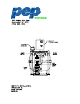
SMF2-FG Series Media Filter Operating & Maintenance Manual GENERAL DESCRIPTION The PEP SMF-FG Series Industrial Water Filters are permanent media type units specifically designed to clean industrial and process water. The PEP SMF-FG filters are designed for side-stream or in-line applications on non-pressurized systems. The SMF-FG filter vessel is constructed of fiberglass reinforced thermoplastic and has a pressure rating of 50 psig (350 kPa).
SMF2-FG Series Media Filter Operating & Maintenance Manual 2. All PEP Industrial Water Filters should be rigidly anchored to the floor or support steel by means of anchor bolts. The SMF-FG has holes suitable for 1/2" (13mm) anchor bolts. 3. After the unit is installed at a permanent location, the pressure gauge and air relief valves should be installed on the top of the filter tank (some units will have vents already installed). The sand media should be loaded into the filter at this time.
SMF2-FG Series Media Filter Operating & Maintenance Manual stress on piping. Check with local, county, or other government authorities to ensure compliance with applicable government industry requirement codes. NOTE: The filter vessel drain plug is located on the tank bottom for 20”, 24” and 30” units, and on the side near the tank bottom for 36”, 42” and 48” units. ACTUATOR REQUIREMENTS PEP SMF-FG filters utilize electric actuators to control the valve action between the filtration and backwash modes.
SMF2-FG Series Media Filter Operating & Maintenance Manual CODE. CHECK WITH LOCAL, COUNTY, OR OTHER GOVERNMENT AUTHORITIES FOR PRESCRIBED REQUIREMENTS. NOTE: CHECK FILTER PUMP NAMEPLATE FOR HORSEPOWER AND AMP DRAW Single Phase Manual Units 1. Install a separate power supply line with circuit breaker protection between the closest branch distribution panel and the pump motor. The full load current for standard models is listed in Table 4. 2.
SMF2-FG Series Media Filter Operating & Maintenance Manual comes preset from the factory to backwash once every 24 hours of running time. For every non-consecutive pin pull-out in a 24 hour cycle the filter will backwash. Each pin represents 15 minutes of a 24-hour period. The filter can only backwash once every 1/2 hour by time clock. For every pin pulled-out consecutively, the filter will backwash once and then lock itself out for 15 minutes multiplied by the number of pins pulled out.
SMF2-FG Series Media Filter Operating & Maintenance Manual filter inlet and outlet water lines to verify they are open. Make sure the pump is primed. Start the pump and fill filter vessel. Wait for all the air in vessel to be released before closing manual air relief valve. 7. Check the voltage and current of all leads on the pump motor. The current amp draw should not exceed the nameplate rating. 8.
SMF2-FG Series Media Filter Operating & Maintenance Manual pressure switch tubing, and filter tank. The unit should be drained when it is to be shut down for any period of time. Refer to the Seasonal Shutdown section of the manual for recommendations. SEASONAL SHUTDOWN The following services should be performed when the unit is to be shut down for a prolonged time period. 1. Shut off all electrical power. 2. Close the shut-off valves in the filter inlet and outlet water lines.
SMF2-FG Series Media Filter Operating & Maintenance Manual PUMP Warning: Disconnect all electrical power prior to performing pump maintenance. Turn the pump shaft by hand. The impeller should spin freely. If not, remove the pre-strainer from the volute and check with a feeler gauge. The clearance between the impeller and volute face is 0.015" (0.38 mm). Adjust the clearance, if necessary, by loosening the setscrews. The impeller and motor shaft are spring-loaded and will slide forward/back.
SMF2-FG Series Media Filter Operating & Maintenance Manual FILTER TANK The filter tank internal components should be visually inspected annually or whenever backwashing does not reduce the pressure of the filter tank to the starting media gauge pressure. On the SMF-FG filters, remove the lid on the top of the tank to inspect the internal components. Note: Always use care and follow proper shutdown procedures.
SMF2-FG Series Media Filter Operating & Maintenance Manual 1. 2. 3. 4. O-ring or gasket for filter tank access port, hand hole and manhole gaskets. O-ring seal or gasket for pump pre-strainer lid (if applicable). Seal kit for pump Transformer fuse (automatic units only). SAFETY PRECAUTIONS All electrical, mechanical and rotating machinery constitute a potential hazard, particularly for those not familiar with its design, construction, and operation.
SMF2-FG Series Media Filter Operating & Maintenance Manual OPERATION AND MAINTENANCE SCHEDULE TYPE OF SERVICE START UP Inspect general condition of unit MONTHLY SEMIANNUALLY SHUTDOWN ANNUALLY X X Check & lubricate clamp on strainer lid X X X Clean basket in pre-strainer tank X X X Inspect O-ring gasket (SMF) X Check pump shaft for free rotation X X Check operation of valves X X Check, lubricate filter tank access port X X X Inspect over-drain assembly & media pack X X X Chec
SMF2-FG Series Media Filter Operating & Maintenance Manual Table 1: Inspection Chart SMF-FG Model Part Filter Tank X Valves & Linkage X Filter Inter-connecting Piping X Pump pre-strainer tank & basket X Pump X NEMA 4X Box (Automatic only) X Filter skid X Pressure gauge, air relief valves, & tees X Media (ship loose) X Table 2: Connection Sizes Filter Model System Water Backwash City Water Backwash Pump Inlet Filter Outlet Waste Outlet Inlet City Water SMF2-FG in / mm in / mm in
SMF2-FG Series Media Filter Operating & Maintenance Manual Table 3: Filter Flow Rates @ 20 gpm/ft2 (13.58 lps/m2) Filter Model SMF2- FG Forward Flow Minimum Backwash Flow Maximum Backwash Flow GPM / LPS GPM / LPS 20 43 / 2.7 32 / 2 43 / 2.7 24 63 / 3.97 47 / 3 63 / 3.97 30 98 / 6.2 74 / 4.7 98 / 6.2 36 141 / 8.89 106 / 6.7 141 / 8.89 42 192 / 12.11 144 / 9 192 / 12.11 48 241 / 15.2 180 / 11.4 241 / 15.
SMF2-FG Series Media Filter Operating & Maintenance Manual Table 5a. Electrical Requirements / Three Phase (60 Hz) PUMP Motor HP / KW Voltage 3φ 60 HZ Full Load Current (Amps) 1 / 0.75 208, 230, 460, 575 4, 3.6, 1.8, 1.4 2 / 1.5 208, 230, 460, 575 7.5, 6.8, 3.4, 2.7 3 / 2.24 208, 230, 460, 575 10.6, 9.6, 4.8, 3.9 5 / 3.73 208, 230, 460, 575 16.7, 15.2, 7.6, 6.1 Table 5b: Electrical Requirements / Three Phase (50Hz) HP / KW Voltage 3φ 50 HZ Full Load Current (Amps) 1 / 0.75 380, 415 1.