VERTICAL GRID DE FILTERS O W N E R’ S M A N U A L INSTALLATION, OPERATION & PARTS MODELS S7D75 S8D110 This manual should be furnished to the end user of this filter; its use will reduce service calls and chance of injury and will lengthen filter life. Sta-Rite Pool/Spa Group U.S. PATENT NO. 4995523 (Other patents pending) 293 Wright Street, Delavan, WI 53115 International: 262-728-5551, FAX: 262-728-7550 www.starite.com Union City, TN • Delavan, WI • Mississauga, Ont.
VERTICAL GRID DE FILTERS To avoId unneeded service calls, prevent possible injuries, and get the most out of your filter, READ THIS MANUAL CAREFULLY! The Sta-Rite System 3 Vertical Grid DE Filter: • Is designed to filter water for swimming pools. • Is an excellent performer; durable, reliable. Table of Contents Safety Instructions .......................................................................................3 General Information.......................................................................
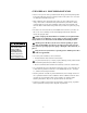
READ AND FOLLOW SAFETY INSTRUCTIONS! This is the safety alert symbol. When you see this symbol on your filter or in this manual, look for one of the following signal words and be alert to the potential for personal injury. warns about hazards that will cause death, serious personal injury, or major property damage if ignored. warns about hazards that can cause death, serious personal injury, or major property damage if ignored.
GENERAL INFORMATION • Clean a new pool as well as possible before filling pool and operating filter. Excess dirt and large particles of foreign matter in the system can cause serious damage to the filter and pump. • With a diatomaceous earth (DE) filter system in place and operating correctly, clean water is returned to the pool faster than pool water is being contaminated.
INSTALLATION Installation of filter should only be done by qualified, licensed personnel. Filter mount must: • Provide weather and freezing protection. • Provide space and lighting for easy access for routine maintenance. (See Figure 1 and Table II, Page 6, for space requirements.) • Be on a reasonably level surface and provide adequate drainage. • Be as close to pool as possible to reduce line loss from pipe friction. Piping: • Piping must conform to local/state plumbing and sanitary codes.
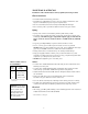
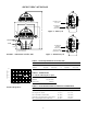
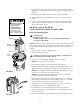
SPECIFICATIONS WATER OUTLET TO POOL D A WATER INLET PUMPED FROM POOL E Figure 2 – Filter Cycle C B OUTLET 7.812(198.4) INLET WATER INLET PUMPED FROM POOL 9.19(233.4) 2" (51mm)Sta-Rite Union Connections WASTE PORT TO SEPARATION TANK FIGURE 1 – Dimensions in inches (mm) Figure 3 – Backwash Cycle TABLE II - SPACE REQUIREMENTS IN INCHES (MM) Model No. S7D75 S8D110 8.
INITIAL START-UP Be sure pump is OFF before starting procedure. Do not operate these filters at more than 50 PSI (345 kPa) under any circumstances! To prevent serious damage to the element fabric, NEVER run you DE filter without a diatomaceous earth precoat! Hazardous pressure. Can cause severe injury or major property damage from tank blow up. Release all pressure and read instructions before working on filter.
FILTER DISASSEMBLY/ ASSEMBLY PROCEDURE To avoid equipment damage and personal injury, never change handle position on control valve while pump is running. BEFORE DISASSEMBLING FILTER: 1. STOP PUMP. 2. OPEN air release valve and drain fitting. 3. WAIT until all pressure is released and water drained from filter tank and system before loosening clamp knobs. Disassembly: 1. Backwash filter according to instructions under “Filter Backwash Procedure”, Page 9. Hazardous pressure.
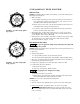
CLEANING THE FILTER 1 When to Clean: 5 4 3 6 2 7 FIGURE 4 - 21" Filter clamp tightening sequence. 1 7 5 Filter Backwash Procedure: 4 3 6 8 2 FIGURE 5 - 25" Filter clamp tightening sequence. NOTICE: If installation does not allow backwashing, use manual cleaning procedure regularly (see Page 10). 1. With a new filter: A. Record filter operating pressure at startup.
9. If any DE remains on grids after backwashing, flush filter elements with garden hose to remove it. Be sure to comply with local code for waste DE disposal. 10. Follow instructions under 'Assembly', Page 8, to reassemble filter. 11. Follow 'Initial Start-up' procedure (Page 7, steps 4, 5, 6 and 7) to restart system. 12. Compare pressure reading on gauge with reading recorded after initial startup. The two readings should be very close; if not, do "Manual Filter Cleaning Procedure", below.
collars may need to be cleaned before reassembly. 10. Follow filter assembly procedure, Page 8. To avoid severe injury or major property damage, exactly follow instructions under “Assembly” (Page 8)! 11. If unit is returning to service, see “Initial Startup”, Page 7. 12. If cleaning is part of seasonal shutdown, see “Winterizing”, Page 12. Hazardous pressure. Can cause severe injury or major property damage from tank blow up. Release all pressure and read instructions before working on filter.
l2. If cleaning is part of seasonal shutdown, see “Winterizing”, Page 12. SYSTEM INSPECTION General: Wash outside of filter with a mild detergent and water. Rinse off with hose. NOTICE: DO NOT use solvents to clean filter; solvents may damage plastic components in system. NOTICE: Open air bleed valve and bleed all air from filter each time pump is stopped and restarted. Weekly Inspection: 1. Skimmer basket- remove debris. 2. Stop pump, release all pressure. Remove trap cover and basket, remove debris. 3.
TROUBLESHOOTING GUIDE 1. Short Cycle between backwashes: NOTICE: Time between backwashes will vary with each installation and between different areas of the country. The following causes and remedies are for cycle times shorter than normal for your area. A. Chlorine residual too low; maintain proper residual (consult pool professional for recommendation). B. Flow rate too high; restrict flow to rated capacity of filter (see instruction plate on filter or specifications on Page 6). C.
15 2 25 30 3 10 0 0 45 5 40 50 60 55 1 5 21 2 3 MODELS S7D75 S8D110 4 5 6 8 7 9 20 10 19 17 11 18 12 14 13 16 14 15 1460 0497 REPAIR PARTS LIST Key No. 1 2 3 4 5 6 7 8 9 10 11 12 13 14 15 16 17 18 19 20 21 • • • Model No. Part Description S7D75 2 Inch Gauge Air Release Valve Close Nipple 1/4 in.
1 2 FILTER ELEMENT ASSEMBLY FOR S7D75 3 4 5 6 7 8 9 1063 0497 10 11 Key No. Part Description No. Used Part No.
STA-RITE LIMITED WARRANTY Pumps, filters, skimmers, underwater lights (except bulbs), accessories and fittings manufactured by Sta-Rite are warranted to be free of defects in material and workmanship for one (1) year from date of installation. Year from date of installation Product specific warranties: HRPB, DEPB, System 3, and PL – Tanks . . . . . . . .10 years Internal filter components and valves . . . . . . . . . 1 year Max-E-Therm – Pool/Spa Heaters . . . . . . . . . . . . .