® IntelliFlo Variable Speed Pump (Compatible with IntelliTouch™ and IntelliComm) Listed Installation and User's Guide IMPORTANT SAFETY INSTRUCTIONS READ AND FOLLOW ALL INSTRUCTIONS SAVE THESE INSTRUCTIONS
Customer Support Sanford, North Carolina (8 A.M. to 5 P.M.) Phone: (800) 831-7133 Moorpark, California (8 A.M. to 5 P.M.) Phone: (800) 831-7133 (Ext. 6312) Fax: (800) 284-4151 Web sites: visit www.pentairpool.com and www.staritepool.com © 2005 Pentair Water Pool and Spa, Inc. All rights reserved This document is subject to change without notice 1620 Hawkins Ave., Sanford, NC 27330 • (919) 566-8000 10951 West Los Angeles Ave.
i Contents Important Safety Precautions ........................................................................................... ii Section 1: Introduction ...................................................................................................... 1 IntelliFlo Overview ................................................................................................................ 1 IntelliFlo Features ............................................................................................
ii Contents (Continued) External Control with IntelliComm Communication Center ....................................... 29 External Control ..................................................................................................... 29 Setting up External Control using IntelliComm.......................................................... 30 Controlling IntelliFlo with IntelliTouch......................................................................... 31 Connecting IntelliFlo to IntelliTouch ...
iii IMPORTANT SAFETY PRECAUTIONS Important Notice: Attention Installer: This manual contains important information about the installation, operation and safe use of this product. This information should be given to the owner and/or operator of this equipment. WARNING — Before installing this product, read and follow all warning notices and instructions which are included. Failure to follow safety warnings and instructions can result in severe injury, death, or property damage.
iv IMPORTANT SAFETY PRECAUTIONS (continued) WARNING — Water temperature in excess of 100° Fahrenheit may be hazardous to your health. Prolonged immersion in hot water may induce hyperthermia. Hyperthermia occurs when the internal temperature of the body reaches a level several degrees above normal body temperature of 98.6° F. (37° C.). The symptoms of hyperthermia include: drowsiness, lethargy, dizziness, fainting, and an increase in the internal temperature of the body.
1 Section 1 Introduction IntelliFlo Overview The IntelliFlo variable-speed pump control system offers pool and spa filter automation and advanced features that include energy conservation and programmable scheduled water features for your pool, spa, cleaner, waterfall, and other applications. The IntelliFlo pump can adapt to any application up to 130 gallons per minute, you simply program IntelliFlo to suit the application. IntelliFlo then dials in the perfect operating conditions.
2 IntelliFlo Features • • • • • • • • • • • • • • • • • Sizes itself to any pool Reduces energy cost by as much as 90% Protects against loss of prime or flow blockage Prevents thermal overload Detects and prevents damage from under and over voltage conditions Protects against freezing Can communicate with an IntelliTouch or IntelliComm system via a two-wire connection Easy to read operator control panel LCD display Operator control panel buttons for pump modes Built-in strainer pot and volute Ultra energy
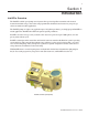
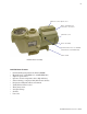
3 Operator control panel cover Drive assembly and electronics enclosure Motor fan cover Motor assembly Communication Port for RS-485 (IntelliTouch and IntelliComm) Motor stand IntelliFlo Motor Assembly IntelliFlo Motor Features • • • • • • • • • • • Permanent Magnet Synchronous Motor (PMSM) High efficiency (3450 RPM 92% and 400 RPM 90%) Superior speed control Operates at lower temperatures due to high efficiency Same technology as deployed in hybrid electric vehicles Designed to withstand outdoor e
4 IntelliFlo Drive Assembly and Control Panel The IntelliFlo drive assembly consists of an operator control panel and the system electronics that drive the 230 VAC single phase (260 VAC~170 VAC) motor. The drive microprocessor controls the motor by changing the frequency of the current it receives together with changing the voltage to control the rotational speed.
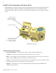
5 Section 2 Operator Control Panel This section describes the operator control panel controls and LEDs. IntelliFlo Operator Control Panel IntelliFlo ® 15 Filter mode Vacuum mode Back Wash Manual mode 1 4 2 3 Es ca pe t lec Se 6 5 14 Menu On Enter 7 Warn. 8 Alarm 9 Feature 1 Feature 2 Start Stop Reset 10 13 11 12 Controls and LEDs 1 Filter button/LED: Starts Filter mode. The LED is on when Filter mode is active. 2 Vacuum button/LED: Starts Vacuum mode.
6 Controls and LEDs (Continued) 9 Arrow buttons: • • • • Up arrow: Move one level up in the menu tree or increase a digit when editing a setting. Down arrow: Move one level down in the menu tree or decrease a digit when editing a setting. Left arrow: Move cursor left one digit when editing a setting. Right arrow: Move cursor right one digit when editing a setting. 10 Feature 1 button: Starts Feature 1 mode. The LED is lit when mode is active. 11 Feature 2 button: Starts Feature 2 mode.
7 Navigating the Menu Structure Before navigating the control panel menu structure, first familiarize yourself with the menu buttons. To change a parameter setting, use the Left and Right arrow buttons to select the digit, then the Up and Down arrow buttons to edit the digit. The following example shows how to set the GPM and priming time in the “Priming” menu (see page 14). PrimingModeExample MENU Menu To set the “Priming” mode settings: 1. Ensure that the green power LED is on and the pump is stopped.
8 Blank Page IntelliFlo Installation and User’s Guide
9 Section 3 Operating IntelliFlo This section describes how to use the IntelliFlo pump control panel. Metering the System The first step to operating and programming IntelliFlo is to know what is being used in the pool system. After the devices are selected you can then set valves for the appropriate features and use the “Manual” mode to measure flow rates for the types or series of devices that require flow.
10 Manual Mode (Continued) To change the Set Flow and Set Speed features: 1. Ensure that the green power LED is on. 2. Press the Manual button (LED is on). 3. Set Flow: Use the Up and Down arrow buttons to select Set Flow, then press the Select button to edit the setting. 4. To change the setting, press the Left and Right arrows to select which digit to modify, then use the Up and Down arrows to change the selected digit. The preset flow values can be set to 15 to 130 GPM (default 50 GPM). 5.
11 Manual Mode (Continued) 9. Press the Start/Stop button (LED is on) to run IntelliFlo in “Manual” mode (LED is on). The pump will start and control the flow or speed using the last settings made. After the button is pressed, the display shows “Running.” To stop IntelliFlo, press the Start/Stop button (LED is off). The display will show “Stopped.” Note: While IntelliFlo is running in Manual mode, you can view the current power consumption and what actual speed is being used. 10.
12 Main Structure MAIN SCREEN POOL DATA (page 13) PRIMING (page 14) FILTER (page 16) TIME / CONTR (page 22) Press MENU button to access menu items Address (68˚ - 104˚ F) Pool Volume (1 - 1000 Kgal) Max Priming Flow (30 - 160 gpm) Max Priming Time (1 - 15 min.) Sys Priming Time (0 - 5 min.) Clean Filter Pressure (1 - 50 min.
13 Pool Data Mode Use the Pool Data menu to configure IntelliFlo for the pool and spa system. From this menu you can set an address for the IntelliFlo pump when connected to an IntelliTouch system, set the volume of pool water, in 1000’s of gallons (kgal) and estimated pool water temperature. To access the Pool Data menu: 1. Ensure that the green power LED is on and the pump is stopped. IntelliFlo ® 12:15 MENU 2. Press the Menu button. Pool Data 3.
14 Priming Mode To “prime” a pump means filling the pump and suction pipe with water. This process evacuates the air from all the suction lines and the pump. It may take several minutes to prime depending on the depth of water, pipe size and length. It is easier to prime a pump if you allow all the air to escape from the pump and pipes. The water cannot enter unless the air can escape. Pumps do not hold prime, the pool piping system has that task.
15 Priming Mode (Continued) 6. To set the System Priming Time: Press the Select button to access the “System Priming Time” setting. After the pump is primed it will take sometime before the system is primed. This time is called “System Priming Time” To enter the maximum system priming time, see step 7. ® 12:54 Priming 15.MIN Max Priming Time Filter Back Wash Vacuum Manual Es ca pe t lec Se Menu The “System Priming Time” value is entered in minutes, from 0 to 5 minutes.
16 Filter Mode IntelliFlo will calculate the required flow rate based on pool size, clean filter pressure, pool turns per day and cycles per day, and will control the motor speed to keep a constant flow. The filter mode can run cycles, power save or features. The IntelliFlo internal scheduler will keep track of which function to run. IntelliFlo is constantly monitoring the filter, when it detects that the system is dirty, it will display an “Alert Service System Soon” message on the control panel display.
17 Filter Mode (Continued) 5. To set the Cycles Per Day: Press the Select button to access the “Cycles Per Day” setting. To edit this setting, see step 6. IntelliFlo uses the Cycles Per Day parameter to calculate how much time it has to complete its filter job. You can program up to four start and stop cycles per day. The more time the IntelliFlo is given to operate the less power and flow will be needed for turning over the pool.
18 Filter Mode (Continued) Filter Cycle Settings Note: The control panel is disabled when the Intelliflo is communicating with an IntelliTouch. "DISPLAY NOT ACTIVE!" will be displayed. NAME VALUE DESCRIPTION Turnovers Per Day 1-8 (Default 1) The number of times per day the volume of water setup in "Pool Volume" will be moved. Cycles per Day 1-4 Cycles (Default 1) The number of cycles (star t and stop) the IntelliFlo must do per day.
19 Filter Mode (Continued) Clean Filter Pressure Example The following example shows the “Clean Filter Pressure” set to 14 PSI. IntelliFlo ® IntelliFlo 1:37 FILTER 10 psi 43.GPM Vacuum Back Wash Manual Filter Vacuum Back Wash On Filter Manual Es ca pe Menu Enter Warn. Enter Warn.
20 Filter Mode (Continued) Using Filter mode with Features mode IntelliFlo will start and stop at programmed filter cycles 1-4. The filter cycles can be overridden by “Feature” (3-9 only) as shown in the example below. This may cause the required filter volume to be achieved earlier. The “Feature” function is allowed to take control during “Filter” mode. When the feature function stops, IntelliFlo will continue in “Filter” mode.
21 Filter Mode (Continued) Flow Control and Filter Mode The Filter Mode feature provides the ability of overcoming head pressure loss to provide the required flow through the plumbing. The flow that the unit can provide is limited by the installed plumbing. If more flow is demanded than the IntelliFlo can provide, it will ramp to full speed and create pressure. The following example shows a ramp as flow increases from 50 to 75 GPM.
22 Time and Contrast Menu Use the “Time and Contr” menu settings to set the IntelliFlo system clock and to adjust the control panel display contrast. The IntelliFlo system clock controls all scheduled start and stop times, functions, and programmed cycles. The system clock can store the correct time for up to 96 hours after power is shut off. After 96 hours the clock must be reset to the correct time. Setting System Time To set the IntelliFlo system clock: 1.
23 Features Mode The Feature mode can be used with water features such as spa, cleaner, waterfalls, etc. You can schedule start and stop times for each feature. All Features are operated using Flow control. The Feature mode and Filter mode are run simultaneously. The three types of features are; Features 1 & 2, Features 3 -9 and M.O. Flo: Features 1 and 2 Feature 1 and Feature 2 run for a pre-defined duration with a specifically set flow.
24 Features Mode (Continued) Feature Settings Name Value Description F1-9 and M.O.
25 Features Mode (Continued) The functions of the Features groups are shown below: How to set up the Feature 1 or 2 (Flow and Duration) mode To access the Features menu: 1. Ensure that the green power LED is on and the pump is stopped. Feature Groups Features 1-2 Features 3-9 MOFlo Flow and Duration Flow, Start / Stop Time Flow, Interval, Length of Interval 2. Press the Menu button. Press the Up or Down arrows to select the “Features” menu.
26 Features 1 – 2 (Flow and Duration) To run Feature 1 or 2 (Flow and Duration) 1. Press the Feature 1 or Feature 2 button, then press the Start/Stop button. The active feature LED will be on until the process is finished. 2. The Features screen will then start to subtract time in minutes from your duration or you can scroll using the Up or Down arrow buttons to see the power, speed, or flow status.
27 3. To enable Feature 3: Press the Select button then the Down arrow button to select Enabled if not already selected. Press the Enter button to save the setting. 4. To set the flow rate for Feature 3: Press the Down arrow button to select “Set Flow” setting. Press the Select button to access the setting. To edit the flow rate (GPM) setting, see step 6. 5. To set the start and stop time for Feature 3: Press the Down arrow button to select “Start Time” or Stop Time” setting.
28 Mo Flo (Modulation Output Flow) M.O. Flo (Modulated Output Flow) is specifically designed for Pentair branded heaters with an IntelliComm, although it can be used for other functions, such as water effects. This feature allows you to have flexibility in flow control if the filter cycle flow is less than needed for certain devices. M.O. Flo also allows you to program intervals of flow separated by a specific duration which can be useful for water effects. To setup the M.O. Flow option: 1.
29 External Control with IntelliComm Communication Center The IntelliFlo can be remotely controlled by the Pentair IntelliComm Communication Center using an optional communications cable (P/N 350122). The IntelliComm provides four pairs of input terminal connections. These inputs are actuated by either 15 - 240 VAC or 15 - 100 VDC. Using the device's inputs, the IntelliFlo external control Programs 1-4 can be controlled.
30 External Control (Continued) Setting up External Control using IntelliComm The IntelliComm communication center is activated by the device voltage when it switches on and off which in turn enables any one of the IntelliFlo Programs 1-4. When the signal stops, the IntelliFlo will default back to it’s cycle programming. The IntelliFlo will always override to its largest command flow rate. Note: The IntelliFlo control panel remains active when the IntelliFlo is connected to the IntelliComm.
31 Controlling IntelliFlo with the IntelliTouch The IntelliFlo pump can be controlled by an IntelliTouch system via the RS-485 communication cable. In this configuration IntelliTouch starts and stops the IntelliFlo. IntelliTouch also rewrites many of the parameters in the IntelliFlo drive's memory, such as the filter cycle start and stop times, pool size and the clock.
32 Connecting IntelliFlo to IntelliTouch (Continued) 6. Strip back the cable conductors ¼”. Insert the wires into the either of the COM PORTS (J7 and J8) screw terminals located on the left side of the Personality board. Secure the wires with the screws. For wiring details, refer to the pin configuration shown below. Note: Multiple wires may be inserted into a single screw terminal.
33 Backwash Mode When the Filter mode has detected that the differential pressure is at the “Clean Filter Pressure” the filter must be cleaned. You need to stop IntelliFlo either by pressing the Backwash button or “Start/Stop” button. IntelliFlo must now be run for a preset cycle time with a preset flow. The flow is adjustable to accommodate the specific filter backwash flow requirement. After the backwash cycle, a rinse cycle, with preset duration time will be executed.
34 Running Backwash mode To start Backwash mode: 1. Press the Backwash button. 2. When running in Backwash mode IntelliFlo will run at the preset backwash flow for the preset backwash time. 3. When the Backwash mode is stopped, manually or after the preset Backwash cycle time, the IntelliFlo will stop and show the “Rinse” menu option. 4. Press the Start Stop button after repositioning the backwash valve to rinse the filter. 5.
35 Vacuum Mode Use Vacuum mode to clean the pool manually. Vacuum mode only operates in flow control. Vacuum mode shuts off all sensors. This mode is identical to Feature 1 and 2 except that you can manually start this mode using the Vacuum button. Safety considerations should be made when setting the Vacuum flow parameter.
36 Blank Page IntelliFlo Installation and User’s Guide
37 Section 4 User Maintenance The following information describes how to service and maintain the IntelliFlo pump. Pump Strainer Basket The strainer, sometimes referred to as the “Hair and Lint Pot,” is in front of the of the pump. Inside there is a basket which must be kept clean of leaves and debris at all times. View the basket through the top see through lid to inspect for leaves and debris.
38 Pump Strainer Basket Service (Continued) 10. Ensure that the lid o-ring is properly placed. Seat the clamp and lid then turn clockwise until the handles are horizontal as shown. 11. Reconnect the communication cable to the pump if required. 12. Switch the power ON at the circuit breaker. Reset the pool time clock to the correct time. WARNING - FILTER OPERATES UNDER HIGH PRESSURE. WHEN ANY PART OF THE CIRCULATING SYSTEM (e.g., LOCK RING, PUMP, FILTER, VALVES, ETC.
39 Winterizing The IntelliFlo’s internal anti-freeze protection is disabled when connected to an IntelliTouch. Freeze protection is provided by selecting YES at the ON WITH FREEZE portion of the IntelliTouch’s appropriate circuit function menu. To re-enable the IntelliFlo’s internal anti-freeze protection, the power to the drive must be cycled off then back on. 1. If the air temperature drops below 35° F the water in the pump can freeze and cause damage. Freeze damage is not warrantable. 2.
40 4. Make sure all electrical connections are clean and tight. 5. Open the air release valve on the filter, and stand clear of the filter. 6. Switch the IntelliFlo on at the circuit breaker. Ensure that the green power LED is on. 7. Press the Manual button (LED on) to place IntelliFlo in manual mode. 8. Use the Up and Down arrows to select Set Speed, then press the Select button to edit the setting. 7. Adjust speed as necessary.
41 Section 5 Installation and Removal The following general information describes how to install the IntelliFlo pump. Attention Installer: Before installing the IntelliFlo pump, read and follow all warning notices, instructions and safety precautions on pages iii and vi. Installing the IntelliFlo Only a qualified service person should install the IntelliFlo. Location 1. Install the pump as close to the pool or spa as possible.
42 Wiring the IntelliFlo To connect the IntelliFlo to AC power: 1. Make sure all electrical breakers and switches are turned off before wiring motor. 2. Make sure that the wiring voltage is 230 VAC. 3. Use #12 AWG for wire runs up to 100 feet and #10 AWG for lengths longer than 100 feet. When in doubt use a heavier gauge (larger diameter) wire. Heavier gauge will allow the motor to run cooler and more efficient. 4. Make sure all electrical connections are clean and tight. 5.
43 Pump Disassembly WARNING — Always disconnect power to the pool pump at the circuit breaker before servicing the pump. Failure to do so could result in death or serious injury to serviceman, pool users or others due to electric shock. Read all servicing instructions before working on the pump. WARNING — DO NOT open the strainer pot if pump fails to prime or if pump has been operating without water in the strainer pot.
44 Pump Disassembly (Continued) 9. To unscrew the impeller from the shaft, twist the impeller counterclockwise. 10. Remove the rotating portion of the mechanical seal from the impeller. 11. Remove the four bolts from the seal plate to the motor, using a 9/16 inch wrench. 12. Place the seal plate face down on a flat surface and tap out the carbon spring seat. 13. Clean the seal plate, seal housing, and the motor shaft.
45 Drive Assembly Removal and Installation To remove the IntelliFlo drive and control panel from the motor assembly: 1. Make sure all electrical breakers and switches are turned off before removing the drive. 2. Disconnect the communication cable from the pump. 3. Open the control panel cover. 4. Remove the three Phillips head screws securing the drive to the motor assembly as shown. CAUTION: TO AVOID ELECTRICAL HAZARD, DO NOT REMOVE THE TAMPER PROOF SCREWS (QTY 4) FROM THE MOTOR ASSEMBLY 5.
46 Illustrated Parts List 22 25 23 26 31 15 3 27 30 20 4 1 32 2 24 23 21 28 17 18 11 13 16 10 6 8 12 5 9 7 14 19 Replacement Parts Item Part No. No. BASKET AQ & WF 15 072184 070429 BOLT HEX HD, 2-56x0.875 s/s, (QTY 4) WASHER 3/8 ID X 7/8 OD .05 THICK 18-8 s/s, (QTY 6) 16 072928 DIFFUSER ASSEMBLY WFE 12 070430 BOLT 3/8 - 16 X 1¼ HEX CAP 18-8 s/s, (QTY 4) 17 073131 IMPELLER WFE 12 1000 SER 18 075713 RUBBER WASHER WFE PUMP Item Part No. No.
47 IntelliFlo Pump Dimensions Intelliflo Flow and Power vs Flow Pump Curve IntelliFlo® Flow and Power vs. Flow 120 3.5 3 2.5 80 P er @ ow Hea d PM 0R 345 @3 450 2 RP M kW Head (Feet of Water) 100 60 1.5 40 Head @ 20 2070 Power @ 20 1 70 RPM RPM 0.
48 Blank Page IntelliFlo Installation and User’s Guide
49 Section 6 Troubleshooting IMPORTANT: Before troubleshooting the IntelliFlo pump, read and follow all warning notices, instructions and safety precautions on pages iii and vi. Alerts and Warnings The IntelliFlo displays all alarms and warnings on the control panel display. When an alarm or warning condition exists, the corresponding LED will be lit on the display. All control panel buttons are disabled until the alarm or warning is acknowledged with the Enter button.
50 General IntelliFlo Troubleshooting Problems Use the following general troubleshooting information to resolve possible problems with your IntelliFlo pump. Note: Turn off power to unit prior to attempting service or repair. Problem Possible Cause Corrective Action Pump failure. (For IntelliFlo aler t display messages, refer to Aler ts and Warning on page 49). Pump will not prime - Air leak in suction. Check suction piping and valve glands on any suction gate valves.
51 Problems and Corrective Action (Continued) Problem Possible Cause Corrective Action Inadequate circulation. (For IntelliFlo aler t display messages, refer to Aler ts and War ning on page 49). Pump overcurrent. Check trap basket; if plugged, tur n pump off and clean basket. Suction/discharge piping is too small. Check and clean pool filter. Circuit breaker trips repeatedly. (For IntelliFlo aler t display messages, refer to Aler ts and War ning on page 49). Excessive motor current. GFCI fault.
52 General Warnings • Never go inside the drive enclosure. There is a capacitor bank that holds a 230 VAC charge even when there is no power to the unit. • IntelliFlo is not submersible • The pump is capable of 160 GPM or 104 feet of head; use caution when installing and programming to limit pumps performance potential with old or questionable equipment • Code requirements for the electrical connection differ from state to state.
53 How to make your pool more energy efficient Swimming pools are great for relaxing, exercising or just having fun. But they also mean higher than average energy bills. The key to saving energy with your pool is to correctly manage the filter pump time, pool temperature and lighting. Consider the following when operating your swimming pool: Using your IntelliFlo pump Your pool needs to be filtered every 24 hours. The time to filter the pool depends on: • • • • The size of your pool.
54 Preventive maintenance Follow a regular program of preventive maintenance, including an annual inspection of the heat exchanger to help maintain heating efficiency. Energy Efficient IntelliFlo pump When its time to replace your old motor and pump assembly, consider using the IntelliFlo variable speed energy-efficient pump. It moves more water more efficiently, and can help you reduce your filter operating time by hours.
55 Notes IntelliFlo Installation and User’s Guide
56 Notes SAVE THESE INSTRUCTIONS IntelliFlo Installation and User’s Guide
Notes
P/N 350075 Rev.