IntelliTouch ScreenLogic User’s Guide
© 2006 Pentair Water Pool and Spa, Inc. 1620 Hawkins Ave., Sanford, NC 27330 • (919) 566-8000 10951 West Los Angeles Ave., Moorpark, CA 93021 • (805) 553-5000 All rights reserved. Information in this document is subject to change without notice. IntelliTouch, IntelliFlo, IntelliBrite, Swimming Colors, MobileTouch, SAm, SAL, and FIBERworks Pentair Pool Products and the Pentair Water Pool and Spa Inc. logo are registered trademarks of Pentair Water Pool and Spa Inc.
i Contents Introduction .............................................................................................. 1 Introduction ............................................................................................................ 1 IntelliTouch System Overview ................................................................................ 1 IntelliTouch System Components .......................................................................... 2 Load or Power Center .........................
ii Contents (Continued) Configuring ScreenLogic ..................................................................... 29 Accessing IntelliTouch ScreenLogic Configuration Program ............................... 30 Installing IntelliTouch ScreenLogic Software on a PC or Laptop (iTC15 Kit only) 30 Start the Configurator Utility on the Tablet or In-Wall Touch Screen ..................... 30 Start ScreenLogic Program .................................................................................
iii Contents (Continued) Using ScreenLogic ................................................................................ 53 Home Screen ...................................................................................................... 56 Main Screen ........................................................................................................ 57 Configuring Pool and Spa Heating System Options ............................................ 59 Change the Pool and Spa Temperature ............
iv Contents (Continued) My Tablet and/or PDA lost the wireless connection to the ScreenLogic Wireless Router or Range Extender. How do I reconnect? ............ 86 I can’t locate the ScreenLogic program on my PDA - How do I install it? ............ 87 PDA First Time Setup Instructions....................................................................... 87 Charging the PDA ................................................................................................
v IMPORTANT SAFETY PRECAUTIONS Important Notice: Attention Installer: This manual contains important information about the installation, operation and safe use of this product. This manual should be given to the owner and/or operator of this equipment. WARNING - Before installing this product, read and follow all warning notices and instructions which are included. Failure to follow safety warnings and instructions can result in severe injury, death, or property damage.
vi IMPORTANT SAFETY PRECAUTIONS (CONTINUED) FCC Regulatory Safety Notice - The wireless products devices have been tested and found to comply with the limits for a Class B digital device, pursuant to Part 15 of the FCC Rules. These limits are designed to provide reasonable protection against harmful interference in a residential installation.
vii IMPORTANT SAFETY PRECAUTIONS (CONTINUED) CAUTION: Danger of explosion if battery is incorrectly replaced. • Replace only with the same type recommended by the manufacturer. • Dispose of used batteries according to the manufacturer’s instructions. • Rechargeable Lithium-ion battery disposal • Unwanted lithium ion battery packs may be returned to the battery manufacturer for disposal.
viii About this User’s Guide This manual describes the how to set up and use IntelliTouch ScreenLogic, including how to configure your IntelliTouch system using the Configurator utility, and how to use the ScreenLogic program to control basic everyday pool and spa operations to advanced setup functions that only need to be performed once. This manual includes the following sections: • Introduction (page 1): IntelliTouch system description.
1 Introduction Welcome! Your Pentair IntelliTouch ScreenLogic Pool and Spa control system will change the way you view pool and spa controls. This innovation in pool and spa automation offers complete freedom for you while having full automation control over your pool, spa, lights, heater, cleaners and much more. You can now schedule multiple start and stop times to control your lights, heater, spa jets, and filter pumps.
2 IntelliTouch System Components The main required components of an IntelliTouch system are the Load or Power Center, IntelliTouch Personality Kits, and the Interfaces: Load or Power Center • • • Load Center: Provides a larger footprint (17" W x 23" H) Includes built-in sub panel (125 AMPS) capable of holding up to eight 1 inch breakers. Also includes five 25 AMP three HP relays, 110/240 V transformer with secondary side circuit protection.
3 IntelliTouch Interfaces Pool and Spa owners can choose one or more of the following interface options to control the IntelliTouch system throughout their home. • iTC15 Kit (P/N 520500) – Includes Protocol Interface Adapter and wireless router that connects to existing Desktop or Laptop PC. This allows control of IntelliTouch pool and spa systems via PC (requires PC with an Ethernet connection, and Windows XP operating system).
4 3 5 9 10 1 7 8 4 2 6 IntelliTouch ScreenLogic in your home 1 Personal Computer (PC): Existing home owner’s PC or Laptop. Connects to a wireless router and the IntelliTouch Protocol adapter for control of IntelliTouch pool/spa systems. Requires a PC/Laptop (Windows XP) with Ethernet/ RJ45 adapter installed. 2 Personal Digital Assistant (PDA): This wireless PDA with a color touch screen enables you to control your pool and spa features using the IntelliTouch ScreenLogic interface.
5 IntelliTouch Interface ScreenLogic Kits The following items are included in your IntelliTouch Interface ScreenLogic Kit. As you unpack your IntelliTouch ScreenLogic Kit, please check to make sure that you received the items listed below. If any item is missing or damaged, contact your authorized dealer, or contact Technical Support (see page viii). PC Interface (iTC15 Kit - P/N 520500) • Protocol adapter. • Wireless router (802.11b/g) with AC adapter.
6 Blank Page IntelliTouch ScreenLogic User’s Guide
7 PDA, in-Wall Touch Screen and Tablet Overview IntelliTouch ScreenLogic User’s Guide
8 Personal Digital Assistant (PDA) Description The iTC25 (P/N 520501) Interface Kit includes a wireless touch screen PDA which is custom configured with the IntelliTouch ScreenLogic Pool and Spa control application. This device also offers a wide range of capabilities. For more detailed information about the PDA, refer to the manufacturers documentation shipped with the device.
9 PDA Front and Side Views (Continued) Power Button: Press the power button to turn the device on or off. Press and hold the power button to dim the display. Repeat to light the display. • • • • When the device is connected to external power and the main battery is fully charged, the power button light is solid green. When the battery charge is low, the power button light flashes amber. When the battery is being charged, the power button light is solid amber.
10 In-Wall Touch Screen The iTC35 (P/N 520502) Interface Kit includes an in-wall color touch screen which is custom configured with the IntelliTouch ScreenLogic Pool and Spa control application. The operating software is Windows CE .NET bringing with it numerous applications, including support for Internet browsing, Windows Media Player, local e-mail client, and word processing. For in-wall touch screen installation instructions, see “In-Wall Touch Screen Installation,” page 97.
11 Tablet Overview The iTC45 (P/N 520503) Interface Kit includes a wireless touch screen Tablet which is custom configured with the IntelliTouch ScreenLogic Pool and Spa control application. Featuring a robust magnesium alloy enclosure, the 2 lb tablet with 8.4 in TFT display is powered by the Intel XScale processor providing “instant-on” capability with extended use between battery recharge. The operating software is Windows CE .
12 Button Tablet Description Functions (Continued) Default Action 6 Cradle USB (ActiveSync) interface: Push to Enable USB (ActiveSync) link between PC and Cradle with device secure on Cradle. Not used by IntelliTouch ScreenLogic program. 7 Launches Internet Explorer Browser: Only works if you are connected to a Broadband Internet connection. 8 Minimize: Desktop Minimize current application and return to Desktop. Does not work when IntelliTouch ScreenLogic is running.
13 Using your ScreenLogic Interface Please read the following important information before operating your ScreenLogic interface. Important Precautions (Tablet, PDA, and In-wall Touch Screen) Before you use this device, please read this manual for setup procedures, safety precautions, and other important information. Please review the contents even if you are an experienced user. If you have any problems, contact Technical Support. For Technical Support contact information refer to page viii.
14 Low Battery Condition (Tablet and PDA) A warning message will be generated during a low battery condition and the Tablet and PDA will shortly thereafter be placed into (Forced) Suspend mode if operation continues without external supply of power. When a low battery condition occurs, the PDA will notify you that its battery is low, then it will automatically turn off the wireless radio to conserve battery life.
15 Installation IntelliTouch ScreenLogic User’s Guide
16 Before You Begin Your IntelliTouch ScreenLogic PDA, wireless Tablet, and in-wall touch screen are pre-configured and ready for operation. The system hardware includes a Protocol adapter, a wireless router, and your choice of wired or wireless interface. The following describes the different set up options which depend on the type of Personality Kit being used: • iTC15 Kit (P/N 520500) – Includes Protocol Interface Adapter and wireless router that connects to existing Desktop or Laptop PC.
17 ScreenLogic Location Requirements The IntelliTouch wireless router and the Protocol adapter must be located inside in a dry environment, preferably near the home owner’s DSL/Cable modem. To ensure optimum wireless connection, placement of the IntelliTouch wireless router inside the home is important. Ideally, the wireless router should be positioned in the room nearest to the pool and spa location or close to where the wireless tablet or PDA will be primarily used.
18 Location Requirements (continued) Cable Distance Limits Depending upon your location requirements, you may choose to have a long Ethernet cable run and a short fourwire cable run or vice-versa. The recommended cable limits are: • • Ethernet cable distance limit = 300 feet Four-wire cable distance limit = 1500 feet Recommended Wireless Router and Protocol adapter Location Note: A first floor installation location is recommended to maximize the wireless signal strength.
19 Wireless router and Protocol adapter with existing Indoor Control Panel (option) In some cases the homeowner will already have an existing IntelliTouch Indoor Control Panel. The fourwire conductor cable used to connect to the ScreenLogic Protocol adapter can tap in the Indoor Control Panel’s four-wire connector or cable.
20 Adding Range Extender Kit for Large Home and Properties For larger homes and properties it may be necessary to install the wireless Range Extender kit (P/N 520561). The wireless Range Extender kit transfers the wireless signal for better coverage where you primarily use your Tablet and/or PDA. The wireless Range Extender kit consists of two wall-plugs that plug into your home’s AC power wall outlets.
21 Connecting without Broadband Internet Access This connection setup is for homeowner’s that do not have a Broadband Internet connection. Note: Use of the PDA, Tablet, or in-wall touch screen does not require the use of a PC. To connect the IntelliTouch ScreenLogic hardware: 1. Connect the Protocol adapter to the wireless router: Connect an Ethernet cable (CAT 5) to the Ethernet RJ45 jack located on the Protocol adapter.
22 Connecting to your Home Network with Broadband Access While not a requirement to run ScreenLogic, IntelliTouch ScreenLogic can coexist with and utilize your existing home network’s Broadband connection. There must be either an Ethernet-based Cable or DSL modem with an established Broadband Internet account from an Internet Service Provider (ISP).
23 Connecting to your Home Network with Broadband Access (Continued) Existing wireless router (mandatory) Range Extender (Ethernet Bridge) wall-plug (Plugs into AC power wall outlet - Connect to LAN Port via Ethernet cable) Wireless Extender wall-plug (Plugs in to AC power wall outlet Located in a room where the Tablet and/or PDA will be primarily used) In-wall Touch Screen Four-wire (22 gauge) (Connects to the Personality board) RJ11 for DSL Coax for Cable INTERNET WAN 1 2 3 4 RJ11 RJ45 (RJ45) D
24 Connect to the Protocol Adapter The IntelliTouch ScreenLogic Protocol adapter is connected to the Personality board located in the Load Center or Power Center via a four-wire cable. Before connecting the cable to the adapter, first determine the length of cable required for the connection. Protocol Adapter Location: The IntelliTouch wireless router and Protocol adapter should be located inside in a dry environment, preferably near the home owners DSL/Cable modem.
25 Connecting to the Personality Board WARNING - Read the following WARNING information before removing the Power/Load Center enclosure high voltage cover-panel. It is required that the main power into the home be switched OFF at the main circuit breaker box whenever the high voltage cover-panel is removed. The main power must also be switched OFF to access the Power/Load Center enclosure low voltage raceway. The following steps describe how to connect the four conductor cable to the Personality board. 1.
26 7. Strip back the cable conductors ¼ in. Insert the four wires into the screw terminals on either COM PORTS (J7 or J8) plug located on the left side of the Personality board. Secure the wires with the four screws. Make sure to match the color coding of the wires: The pin numbers and wire color codes are: 1 2 3 4 BLK = Ground GRN = -DT YEL = +DT RED = +15 VDC Note: Multiple wires may be inserted into a single screw terminal.
27 Start up the IntelliTouch ScreenLogic System for the first time After the ScreenLogic Protocol adapter and wireless router are installed, power up the system and verify that all cables are properly connected. To start up the system 1. Power up the Load Center and Protocol adapter: Switch the main power on to the Load Center. The Protocol adapter will also be switched on and its RED power LED should be lit.
28 Blank Page IntelliTouch ScreenLogic User’s Guide
29 Configuring ScreenLogic IntelliTouch ScreenLogic User’s Guide
30 Accessing IntelliTouch ScreenLogic Configuration Program This section describes the Configurator utility dialogs used to configure ScreenLogic. Follow the Configurator utility dialogs, Steps 1 through 5 to configure ScreenLogic for the installed IntelliTouch equipment. The Configurator utility should display upon powering up your Tablet, or in-wall Touch Screen.
31 Start ScreenLogic Program To start ScreenLogic after using the Configurator utility: 1. After completing Steps 1 through 5 of the Configurator utility, click the Finish button. The Configurator utility main screen will display. 2. Click the Start ScreenLogic button. To start ScreenLogic from the Desktop: 1. Double-click the IntelliTouch ScreenLogic icon on your Desktop. 2. Click the Start ScreenLogic button.
32 ScreenLogic Configuration and Maintenance Screen The Configurator utility opening screen displays the type of IntelliTouch system equipment, firmware and software versions being used. From this screen you can start the Configurator utility to configure ScreenLogic for the IntelliTouch system, or start the ScreenLogic program. • • To start the Configurator utility: Tap the Configure IntelliTouch button, read the warning message and tap Continue.
33 General Settings (Step 1 of 5) Continued Name Description Clock T h e d a t e & t i m e s e t i n t h e C o n f i g u ra t o r u t i l i t y s e t s a l l s y s t e m c l o ck s fo r t h e P DA , I n - Wa l l t o u c h s c r e e n , Ta bl e t , I n t e l l i To u c h O u t d o o r C o n t r o l Pa n e l , a n d I n d o o r C o n t r o l Pa n e l .
34 Changing the Display to Show Fahrenheit to Celsius Temperature set point and actual temperature settings are displayed on the Main screen in either Fahrenheit or Celsius. To change the temperature scale: 1. Start the ScreenLogic Configurator utility, and tap Configure IntelliTouch. 2. On the General Setting page under Temperature Scale, tap either Fahrenheit or Celsius. 3. Tap Finish when done to save the setting.
35 Setup Circuits (Step 2 of 5) Name Description Setup Circuits Displays the available circuits for the system. Load Center: Displays the installed Load Center or Expansion Center(s). Circuit: Displays the available AUX circuits and Feature circuits (1-10). Depending on the model of the IntelliTouch system, the number of AUX circuits may vary. AUX circuits are located on the Personality board. Circuit Name: Assigned circuit name. Circuit Function: Assigned circuit function.
36 Setup Circuits (Step 2 of 5) Continued Special Lights Button Use this button to display the “Special Lights” dialog. Lights displayed in this dialog are circuits that are assigned as “Lights.” All Lights assigned in this dialog will be controlled by the All Off, All On, Color Set, Color Sync, and Color Swim buttons on the Lights screen. Up to 12 SAm, SAL, lights and the Color Wheel can be configured to use the Color Set, Color Sync, and Color Swim lighting features.
37 Feature Macro Circuits Overview Feature Macro Circuits can control equipment that is not controlled by AUX circuits. In general, AUX circuits are used for high voltage equipment like pumps and lights, whereas Feature Macro Circuits are used for low voltage equipment like valve actuators. However, Feature Macro Circuits can go beyond this definition, and be used in other creative ways.
38 Assign a Circuit Name and Function Note: Before you assign circuit names in ScreenLogic, write down the circuit names and assigned buttons on the Outdoor Control Panel (in the Load Center). The circuit names you assign in ScreenLogic should match the button labels on the Outdoor Control Panel. Circuit Functions let you assign special logic to the circuits. For example, when setting up an automatic pool cleaner pump, you would assign the circuit function MASTER CLEANER.
39 IntelliTouch Circuit Functions The following Circuit Functions allow you to assign special logic to the circuits. Note: To ensure proper operation, some circuits shown below will only display on certain screens. For example, SAm and SAL Lights will always display on the Lights screen, not on the Main screen. Generic A circuit with no special logic. Simple On/Off control of a circuit with all the programmable capabilities.
40 IntelliTouch Circuit Names AERATOR AIR BLOWER AUX 1 AUX 2 AUX 3 AUX 4 AUX 5 AUX 6 AUX 7 AUX 8 AUX 9 AUX 10 BACKWASH BACK LIGHT BBQ LIGHT BEACH LIGHT BENCH BLOWER BOOSTER PUMP BUG LIGHT CABANA LTS CHEM.
41 Creating a Feature Circuit Macro Feature Macros give you the ability to combine various circuits together so a single button can operate them all at once. For example, you could create a Macro that would give you one button that turns on your spa, spa light, fountain, fountain light, and patio lights. A Macro also has the capability to switch a circuit off. You can assign a name to your Macro from the list of IntelliTouch circuit names.
42 Creating Custom Names for Auxiliary Circuits There are nearly 100 circuit names stored in the IntelliTouch software (see page 40). If you cannot find one to fit your application you can create up to 20 custom names. To create a custom circuit name: 1. 2. 3. 4. 5. Start the ScreenLogic Configurator and tap Configure IntelliTouch. Tap Next on the General Setting page. The Setup Circuits (Step 2 of 5) page is displayed. Select an AUX circuit from the main list. Tap the Set Custom Names button.
43 Configure Other Equipment (Step 3 of 5) Name Description Valve Assignments D i s p l ay s t h e c i r c u i t s a s s i g n e d t o va l ve s. A l l I n t e l l i To u c h s y s t e m s c a n c o n t r o l t w o a u x i l i a r y v a l v e a c t u a t o r s ( A a n d B ) fo r a p p l i c a t i o n s s u c h a s s o l a r h e a t i n g a n d w a t e r fe a t u r e s .
44 Configure Other Equipment (Step 3 of 5) - Continued Name Description Pool/Spa - Solar Equipment Po o l / S p a e q u i p m e n t o p t i o n s i n d i c a t e s s h a r e d e q u i p m e n t . I f d u a l b o d y e q u i p m e n t i s b e i n g u s e d , Po o l a n d S p a o p t i o n s a r e d i s p l ay e d , e a c h w i t h t h e i r o w n s e t s o f e q u i p m e n t . S o l a r P r e s e n t : S o l a r h e a t i n g i s a va i l a b l e .
45 Configuring Valve Actuators To assign a valve actuator: 1. Start the ScreenLogic Configurator and tap Configure IntelliTouch. 2. Tap Next on the General Setting page and on the Setup Circuits page. The Configure Other Equipment (Step 3 of 5) page is displayed. 3. Select the Load Center or Expansion Center(s) and the AUX valve actuator (A, B) you wish to configure from the Valve Assignments list.
46 Setting up Additional Equipment The following describes how to set up any special equipment that may be attached. Your system may or may not have this equipment installed. The following information describes: • Setting up a two-speed pump - Setup circuits that switch the filter pump from low to high speed. • Setup Solar equipment - Enable solar or heat pump. • Cool-down cycle for the heater - Set a cool-down cycle for heaters that require it.
47 Setup Solar Equipment and Heat pump option Solar equipment is configured in the “Configure Other Equipment (Step 3 of 5)” dialog, page 43. To configure solar equipment: 1. Start the ScreenLogic Configurator and tap Configure IntelliTouch. 2. Tap Next on the General Setting page and on the Setup Circuits page. The Configure Other Equipment (Step 3 of 5) page is displayed. For i10+3D Dual Equipment, tap the Solar present check box for each body of water with solar heating. 3.
48 Enable Manual Spa Heat Control If this option is selected, your spa will begin to heat whenever it is manually turned on, (by pressing the Spa button on the ScreenLogic main screen), even if the heater is set to OFF. Your spa will also begin to heat when turned on by the spa-side remote, or QT4 wireless remote. This feature allows you to program your spa to filter daily with the heater set to off, and then be ready to heat whenever the SPA button is pressed manually on the ScreenLogic Main screen.
49 Configure IntelliFlo (Step 4 of 5) IntelliTouch can support up to eight IntelliFlo and four IntelliFlo 4 pumps in any combination with up to eight pumps. For more information refer to the IntelliFlo Installation and User’s Guide (P/N 350075).
50 Configure IntelliFlo (Step 4 of 5) - Continued Filtering dialog Pool filtering schedules (start/stop times) are only used for filtering. The pump only allows four such events to exist. These schedules for the circuit (pool) are then transferred to the pump, and used to calculate the energy saving / minimum speed function of the IntelliFlo for the basic filter mode. See page 50 for details.
51 Configure IntelliFlo (Step 4 of 5) - Continued Filtering dialog (Continued) Name Description Vacuum Parameters U s e t h e Va c u u m m o d e t o c l e a n t h e p o o l m a nu a l l y. To o p e ra t e t h e p u m p i n Va c u u m m o d e, p l a c e t h e I n t e l l i To u c h o u t d o o r c o n t r o l p a n e l i n “ S e r v i c e M o d e , ” a n d s t o p t h e I n t e l l i F l o p u m p.
52 Configure IntelliFlo (Step 4 of 5) - Continued Filtering dialog (Continued) Name Description System Max Time 0 - 5 m i n . ( D e fa u l t 0 m i n . ) - T h e a v e r a g e p u m p w i l l p r i m e i n a s h o r t per iod of time because the pump has the ability to monitor itself to m a k e s u r e i t i s p r i m e d .
53 Configure iS10 Spa-Side Remote (Step 5 of 5) Note: For information about configuring switches on the iS10 Spa Side remote, refer to “Configure iS4, iS10 and QT4 QuickTouch,” page 54. Name Description iS10 #1, #2, #3, #4 A s s i g n c i r c u i t s fo r t h e i n s t a l l e d i S 1 0 S p a - S i d e R e m o t e s . Button 1, 2, 3, 4, 5 (Top Row) U s e t h e d r o p - d o w n b ox t o s e l e c t a n a v a i l a b l e c i r c u i t fo r t h e t o p r o w bu t t o n s 1 , 2 , 3 , 4 , a n d 5 .
54 Configure iS4, iS10, and QT4 QuickTouch You can specify any iS4, iS10, or QT4 spa-side remote button to control different functions. To configure the Spa-Side remotes: 1. Start the ScreenLogic Configurator utility and click Configure IntelliTouch. 2. Click Next on the General Setting, Setup Circuits and the Configure Other Equipment screen. The Configure Spa-Side Remotes (Step 5 of 5) page is displayed. 3. Select the previously assigned circuit names that will control a valve.
55 Using ScreenLogic IntelliTouch ScreenLogic User’s Guide
56 Home Screen The Home screen can be configured to display the current time, date and weather conditions for your location as well as system information. Tablet with Broadband Internet connection PDA with Broadband Internet connection Name Description Current Conditions Depending on how ScreenLogic is configured, the Home screen can display weather conditions for your location, or system information. These settings are configured on the "General Settings" page in the Configurator utility.
57 Main Screen The Pool/Spa Main screen displays the main control buttons for the pool, spa, and user defined water features. Pool control button: Switches on Filter Pump and fires heater. Shared equipment systems (i5, i7+3, i9+3); rotates valves to pool position. Pool/Spa heat controls: The Heat Mode switches control the current heat source being used. For shared equipment: When both Heat Mode buttons for the pool and spa are set to on, if the Pool button is switched on, the Spa button is off.
58 Main Screen (Continued) The Pool/Spa Main tab screen displays the main control for the pool, spa, and water features. Name Description Pool/Spa/Water Features Displayed circuit buttons are user assigned as configured in the Configurator utility. For more information about configuring ScreenLogic, refer to page 32. User defined circuit names can be assigned to any of the displayed buttons.
59 Main Screen (Continued) Name Description Water Features The following circuit buttons are examples of circuits that you might display under Water Features. The folowing buttons displayed are defined in the Configurator. For more information about displaying buttons on the main screen, refer to “Setup circuits (Step 2 of 5),” page 35 and “Display a Circuit Function Button on the Main Screen,” page 42 Waterfall button: This Feature Macro circuit has been assigned as a Waterfall.
60 Change the Pool and Spa Temperature All pool and spa heat modes and temperature controls are located on the Main screen. The pool or spa will heat to the settings specified on this screen. Changing Pool Heat Settings To raise the pool water temperature: 1. From the main screen choose Heater, Solar Preferred or Solar in the Heat Mode selection. 2. Tap the pool Warmer button. The pool will heat to the settings specified as indicated by the Set Point.
61 Color Lights Tab For lights to display in the Color Lights screen, and for the Special Lights buttons to work, you must first assign the light in the Special Lights dialog. For more information, refer to Setup Circuits (Step 2 of 5), page 35. From the Lights screen you can switch lights on or off and dim selected incandescent lights. Pentair SAm and SAL lights cannot be dimmed.
62 Lights Screen (Continued) Name Description Special Lights Buttons For lights to display in this screen, and for the Special Lights buttons to work, you must first assign the light in the Special Lights dialog. For more information, refer to Setup Circuits (Step 2 of 5), page 35. All Off: Switches off all lights that have been assigned in the Special Lights dialog in step 2 of the Configurator utility (see page 35).
63 Special Lighting Features If you have at least one Pentair SAm and/or SAL or IntelliBrite, and/or FIBERworks lighting systems, you can use the special Color Set, Color Swim and Color Sync lighting features to change the lighting settings. Up to 12 of these light systems can be independently controlled from the Lights screen.
64 Lights Screen: Configure Set Colors Tab (Color Set) The Configure Set Colors screen displays color selection, and control modes for the Pentair SAm, SAL, and FIBERworks color lights. The Pentair Color Set, Color Sync, and Color Swim features are only available for IntelliTouch models i7+3, i9+3, i9+3S, and i10+3D. Before SAm and SAL lights display on this screen, circuits must first be assigned in the “Setup Circuits” page of the Configurator utility, then selected in the “Special Lights” dialog.
65 Lights Screen: Configure Swimming Colors Tab (Continued) Before SAm, SAL, or IntelliBrite lights display on this screen, circuits must first be assigned in the “Setup Circuits” page of the Configurator utility, then selected in the “Special Lights” dialog. For more information, refer to “Set Circuits (Step 2 of 5),” page 35. Name Description Configure Colors Swim Pool SAM 1: Use the side arrow buttons to increase or decrease the delay time in seconds, between the Pool SAM 1and SAM 2 lights.
66 Color Set Lighting Feature The Color Set feature allows any combination of up to 12 SAm, SAL, IntelliBrite, or FIBERworks lighting circuits to be preset to specific colors. This feature requires at least one SAm, SAL, IntelliBrite, or FIBERworks lighting product controlled by separate AUX circuits. To set up Color Set lights: 1. From the Main screen, tap the Lights tab. 2. Tap the Configure Colors tab. 3. Tap the color for SAm, SAL, IntelliBrite, or FIBERworks lights.
67 Color Sync This feature switches all SAm, SAL, IntelliBrite and FIBERworks colored lights on and synchronizes the lights. To synchronize lights: 1. From the Main screen, tap the Lights tab. 2. Tap the Color Sync button to activate all color changing lights to synchronize with each other. The process may take up to a minute. The displayed red bar indicates the progress.
68 Lights Screen: IntelliBrite Before the configured IntelliBrite lights display on this screen, circuits must first be assigned in the “Setup Circuits (Step 2 of 5)” dialog of the Configurator utility, then selected in the “Special Lights” dialog. For more information, refer to “Set Circuits (Step 2 of 5),” page 35. Using the IntelliBrite buttons, you can select color show modes or fixed colors, and recall a previously captured custom color.
69 Schedule Screen From the Schedule screen you can schedule when to switch on and off lights, heater, spa jets, and the filter pump. You can also schedule which heat mode to use and also change the heat set point if necessary. Name Description Options - Left/Right Arrows Circuit: Name of the circuit to use in schedule. Use the side arrows to select the desired circuit. Start Time: Scheduled start time. Use the side arrows to select the time when the circuit is to be switched on.
70 Schedule Feature Use the Schedule feature to program when you want to automatically run equipment such as pool filtration or lights. Any circuit (auxiliary, feature, or macro) can be set to switch on and off for all days of the week, or for individual days. Up to 99 programs may be created for all circuits combined. The following describes how to schedule a daily program: To program the daily timed circuits 1. From the main screen, tap the Schedule tab. 2. Tap Add Program to add a new schedule. 3.
71 Schedule: Run Once Screen The “Run Once” feature enables you to automatically switch equipment on for one time. For example, you can preprogram your spa to start heating every Sunday at 10 AM to 10 PM. Name Description Circuit: Name of the circuit to use in schedule. Use the side arrows to select the desired circuit. Start Time: Scheduled start time. Use the side arrows to select the time when the circuit is to be switched on. Stop Time: Scheduled stop time.
72 Run-Once Timer Use the Run-Once timer feature to program a circuit to automatically switch equipment on for one time. Unlike the Schedule regular timer, this once-only timer does not repeat. For example, you could set up the program to preheat your spa ready for your arrival. After the programmed Run-Once circuit is completed, it is automatically erased. The circuit must be turned off manually or wait for the 12 hour automatic shut off.
73 Schedule: Egg Timer Screen The Egg Timer feature (count down timer) allows you to define the run time for lighting, spa, spa jets, and other circuits. Equipment can be set to be on for one minute to 23 hours 45 minutes. The factory default duration time is 12 hours. Note: If a power outage occurs during a scheduled count down, the Egg Timer feature will not switch the equipment back on. Name Description Circuit: Name of the circuit to use in schedule.
74 Setting the Egg Timer (Count Down) The Egg Timer count down feature allows you to define the run time for different circuits. For example, whenever you manually switch your spa on, you would like it to automatically turn off in two hours. Use the Egg Timer circuit to set an automatic shut-off time. The time period can be anywhere from 1 minute to 24 hours. The Egg Timer is also a useful feature for turning off lighting and spa jets.
75 History Screen The History screen displays historical usage data for your pool, spa, heater, lights, and solar, as well as pool, spa, and air temperatures. The usage information can be useful for tracking the operation and efficiency of your system. Name Description Zoom In/Zoom Out Use the Zoom In and Zoom Out button to change the time period displayed by Month, Week, Day, or Hour. Use the Previous and Next buttons to scroll through the time display.
76 Equipment: System Status Screen The Equipment System Status screen displays the current status of the system. The system water and air senors are constantly monitored for errors. If a sensor error is detected, the displayed error is highlighted in yellow. Also, from this screen you can cancel delays that might be setup for your pool cleaner or pump. You can also Disable or Enable the Spa-side remote. Name Description System Errors Displays IntelliTouch sensor error informaton.
77 System Error Messages If a system error has occurred with IntelliTouch equipment, the displayed error message is displayed in yellow. System Delay Cancel Feature For convenience, on a one time basis, the Cancel Delays feature will cancel the following safety delays which can be set up in the IntelliTouch system. Please note there is generally not a need to cancel any of these delays except for servicing or testing the system.
78 Equipment: Chlorinator Screen Use the Equipment screen to control various system functions and view the system status. Chlorinator Status and Controls Screen To access the Chlorinator status and controls screen: 1. From the main ScreenLogic screen, tap the Equipment and Chlorinator tab. The chlorinator screen shows: • Chlorinator Status: Shows the current chlorinator operating condition. If an error is detected, the displayed error message box is highlighted in yellow.
79 Equipment: IntelliFlo Screen From this screen you can view the current IntelliFlo pump error conditions, start or stop the IntelliFlo pump, and adjust the GPM for each pump circuit. The pump’s power usage, RPM (IntelliFlo 4x160), and GPM (IntelliFlo) status are also displayed. IntelliFlo Status and IntelliFlo Controls Screen To access the IntelliFlo status and controls screen: 1. From the main ScreenLogic screen, tap the Equipment and IntelliFlo #1 Pool tab.
80 IntelliFlo Status and IntelliFlo Controls Screen (Continued) • IntelliFlo Output (Pump Off/Pump On): The Pump Off box is displayed in yellow when the pump is off and not operating. The Pump On box is displayed in yellow when the pump is operating. The Power Usage (Watts), RPM, and Flow (GPM) display the current status while the pump is operating.
81 IntelliFlo Status and IntelliFlo 4x160 Controls Screen To access the IntelliFlo 4x160 status and controls screen: 1. From the main ScreenLogic screen, tap the Equipment and IntelliFlo 4x160 tab. When multiple pumps are installed, the number (address) of the pumps is also displayed. The IntelliFlo screen displays the following: • Status: See page 79 for details. • Flow Rate Settings/Buttons: Displays the assigned pump circuits on and off buttons.
82 Blank Page IntelliTouch ScreenLogic User’s Guide
83 Frequently Asked Questions (FAQs) and Troubleshooting IntelliTouch ScreenLogic User’s Guide
84 ScreenLogic Tips and FAQs Use the following information to resolve general ScreenLogic operation issues. ScreenLogic Technical Support Questions Before contacting Pentair Water Technical Support, please note that Technical Support personnel can only assist with relevant questions regarding IntelliTouch ScreenLogic hardware and software. IntelliTouch ScreenLogic can only be used with the provided ScreenLogic PDA, Tablet, and in-wall Touch Screen devices.
85 How do I exit the ScreenLogic program while using the Tablet or In-wall Touch Screen? Press the first button (from the left side) on the front of the Tablet or In-wall touch screen to display the virtual keyboard. Tap the Ctrl key, then the Q key to exit the ScreenLogic program. ScreenLogic Error Messages If a system error has occurred with the IntelliTouch equipment, a message is displayed in the System Status box. 1. From the ScreenLogic main screen, tap the Equipment tab. 2.
86 My Tablet and/or PDA lost the wireless connection to the ScreenLogic Wireless Router or Range Extender. How do I reconnect? The Tablet and PDA are always searching for an available wireless signal within range of your wireless router and will automatically try to reconnect to the last successful wireless connection. If your Tablet does not automatically connect to the ScreenLogic wireless router, a red X displays on top of the Internet connection icon in the system task tray as shown below.
87 I can’t locate the ScreenLogic program on my PDA - How do I install it? PDA First Time Setup Instructions Before you can use your PDA to operate your ScreenLogic system, you need to setup the ScreenLogic PDA program. Before starting, make sure the PDA is in its cradle with the power connected. Charging the PDA You need to charge the main battery and internal backup battery from empty to full. This takes about 8 hours the first time and 4 hours thereafter, whether the device is on or off.
88 10. Select the network “Pentair(x) where x is your network number. Select the “Internet” button and tap “Connect”. 11. Your ScreenLogic network key is required. Your WEP Encryption Key (10 digit number) is located on the bottom of your ScreenLogic wireless router. 12. Place the cursor in the key field to open the virtual keyboard. Enter the 10 digit WEP Encryption key (i.e. 1111111111). 13. Tap OK. 14. The device will search and connect to the ScreenLogic wireless router. 15.
89 PDA Tips and FAQs Your PDA is pre-configured at that factory and is ready to use once the Protocol adapter and ScreenLogic wireless router are installed. While it is charging, you can use and configure the PDA. The charging cradle charges the battery and provides power for normal operation. When you first switch on the PDA, you will see the boot screen that is followed by the Microsoft Windows Mobile desktop.
90 Do I need to load any software to get started? The Digital Tablet, PDA, and in-wall Touch Screen comes pre-installed with all the software you will need to surf the Internet, set up e-mail, run local applications, and interact with servers and PCs. These devices provide a means to install new software that may enhance the function and value of the device. Note: Such applications are not supported by Pentair Water.
91 “Connecting Please Wait” message If the Tablet has entered a suspend state, when you switch it back on, it will take a few seconds to reconnect to the ScreenLogic wireless router. If it has trouble reconnecting, move closer to the wireless router. It the Tablet is still non-responsive, hold the Suspend button for four seconds until the Tablet reboots. Wait a few seconds, and press the Suspend button. The Tablet will restart an automatic start the ScreenLogic configuration program.
92 The Tablet comes with protective rubber grip handles and a shoulder strap – what do they offer and how do I use them? The protective handles when properly secured around the device offers an enhanced handling experience with protection against bumps and knocks, up to a three-foot drop. Use the shoulder strap hooked onto the protective jacket for hands-free portability. The jacket has four slots to allow flexibility in connection to the shoulder strap.
93 IntelliFlo Alarms and Warnings The IntelliFlo displays all alarms and warnings on the control panel display. When an alarm or warning condition exists, the corresponding LED will be lit on the display. All control panel buttons are disabled until the alarm or warning is acknowledged with the Enter button. Press the Reset button to clear the alarm once the fault condition has been resolved. Note: The IntelliFlo pump will not start if the impeller is rotating.
94 IntelliFlo 4x160 Alarm and Warnings The IntelliFlo 4 alarm and warnings are indicated by flashing LEDs on the control panel. For example, if a “Drive Temperature” warning occurs, the LED will blink two times, then Off, then blink two times. This sequence is repeated until the condition is cleared. • Warning condition: If a warning condition occurs the pump will be continue to run but at a reduced speed. The Green LED executes a sequence of blinks to indicate which alarm or warning has occurred.
95 Appendix IntelliTouch ScreenLogic User’s Guide
96 The wireless router that came with my ScreenLogic kit does not reliably reach the area where I primarily use my Tablet and/or PDA If it is not practical to place the ScreenLogic wireless router close to the primary operating location of your wireless Tablet or PDA, you can purchase a Range Extender kit. This kit includes two wall plugs; the Ethernet Bridge and the wireless Access Point that plug into you home’s AC wall outlets.
97 ScreenLogic Wireless Connection Kit The ScreenLogic Wireless Connection kit (P/N 520639) consists of two wireless 900 Mhz transceivers which provides a wireless connection between the ScreenLogic Protocol adapter and the IntelliTouch Load Center located at the equipment pad. This wireless connection eliminates the existing hard wire connection from inside your home to the equipment pad. The diagram below shows the wireless transceiver locations.
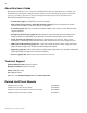
98 Connecting remotely to your system Using the “ScreenLogic Connect” utility you can control your pool and spa operations remotely from your laptop computer over the Internet or from your local networked computer in your house. You can download the remote connection utility from www.pentairpool.com. To connect remotely to your system: 1. After installing the “ScreenLogic Connect” utility, click the “ScreenLogic Connect” icon on your desktop to start the program. 2.
99 HomeLogic Management and Control Solution HomeLogic is the industry leader in home management and automation control systems. The HomeLogic OneHome system provides cost effective automation control solutions for your home including: • • • • • • Home climate thermostat control Home audio Interior home lighting Video surveillance Exterior security lighting Messaging, and much more OneHome automation systems can interface with any computer in the home as well as remote access over the Internet.
100 In-Wall Touch Screen Installation The iTC35 (P/N 520502) IntelliTouch ScreenLogic In-wall Touch Screen interface comes custom configured with the IntelliTouch ScreenLogic Pool and Spa control application. The in-wall touch screen device consists of the following components: Main unit: The electronics and Display assembly. Snap-on front cover or bezel. Rear metal housing. Fits into wall opening (mating screws for Main unit provided).
101 To install the in-wall Touch Screen device: 1. Ensure that no electrical power is being supplied to the device. 2. Prepare the Ethernet cable and AC power cable ready to route through the opening in the lower rear housing. 3. Remove the lower knockouts from rear metal housing. 4. Mount the rear metal housing into the wall frame opening. Secure the rear metal housing to the wall frame with the appropriate number of screws.
102 Glossary +3 IntelliTouch Systems: Feature Circuits, Macro circuits, and Color Set, Color Swim lighting features are only available with IntelliTouch +3 system models. The IntelliTouch +3 system models are: i7+3 (P/N 520505), i9+3S (P/N 520508), i9+3 (P/N 520509), i10+3 (P/N 520510). For more information, refer to “IntelliTouch Personality Kits,” page 2. 802.11: Refers to a family of specifications developed by the IEEE for Wireless LAN technology. 802.
103 Glossary (continued) Load Center: Metal enclosure with power relays, transformer, and circuit breakers. The Load Center is Installed prior to Personality Kit installation. Used for distributing power for controlling IntelliTouch Systems. Also known as the “sub-panel.” Low Voltage Compartment: Top compartment of Load Center for all low voltage wiring. Low Voltage Raceway: Vertical space in the left side of Power/Load Center for low voltage cabling.
104 Notes IntelliTouch ScreenLogic User’s Guide
P/N 520493 - Rev.