INTELLIMASTER VARIABLE SPEED CONTROLLER USER MANUAL Should the installer or owner be unfamiliar with the correct installation and/or operation of this type of equipment, please contact the distributor or manufacturer for the correct advice before proceeding with the installation or operation of this product. ONGA.COM.
SAFETY INSTRUCTIONS Please read the IMPORTANT SAFETY INFORMATION below, and all Warning and Caution information elsewhere.Please read the SAFETY INSTRUCTIONS below. IMPORTANT Danger : Indicates a risk of electric shock, which, if not avoided, could result in damage to the equipment and possible injury or death. Danger : Indicates a potentially hazardous situation other than electrical, which if not avoided, could result in damage to property.
TABLE OF CONTENTS Features / Functions ..................................................................................... 2 Control Key Description................................................................................. 3 Quick Settings ............................................................................................... 3 Technical Characteristics ............................................................................ 4 Parallel Operation ........................................
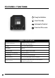
FEATURES / FUNCTIONS Features / Functions 1-1 Easy Installation Easy Installation User Friendly User Friendly Auto Control Control Automatic Constant Pressure Constant Pressure Content Operation Method Display Language Individual Inverter Operation ( Parallel up to 3 pumps ) 2.
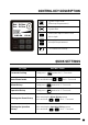
Key Description 1-2 CONTROL KEY DESCRIPTION Icon (Entering the paramters) Set. 2.0 bar Cur. 2.0 bar 0.00 Hz Description System Stop/ Mode System Stop/ Mode (Entering the paramters) System Run System Run Moving the digit locations Moving the digit locations from from left to right left to right 0.
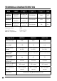
TECHNICAL CHARACTERISTICS Pump Model Controller Model Input Voltage [V] Output Voltage [V] Output Current [A] Motor [kW] IMH750K PVFD0750S (810960) 230V AC 1PH +/- 10% 3 X 220/240 2.4A 0.75 IMH1100K PVFD1500S (810961) 230V AC 1PH +/- 10% 3 X 220/240 4.7A 1.5 IMH2200K PVFD2200S (810962) 230V AC 1PH +/- 10% 3 X 220/240 7.1A 2.
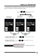
Parallel Operation 1-4 Parallel Operation 1-4 To set parallel operation, change the operation method to the auto operation mode. PARALLEL OPERATION NOTE: Up to 3 pumps can be linked and operated in parallel. To set parallel operation, change the operation method to the auto operation mode. *Note: Up to 3 pumps can change be parrallel operated.* To set parallel operation, the operation method to the auto operation mode. *Note: Up to 3 pumps can be parrallelPress operated.
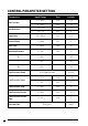
CONTROL PARAMETER SETTING Parameters Input Range Unit Default 0.1 ~ 20.0 bar 3.5 10 ~ 300 psi 30 -3.0 ~ -0.2 bar -0.3 -50 ~ -3 psi -5 3.0 ~ 999.9 sec 5.0 Restart Delay 0 ~ 9999 sec 0 Shift Time 0 ~ 9999 Min 60 Maximum Runtime 0 ~ 999 Min 0 P 1 ~ 200 - 25 I 1 ~ 200 - 40 D 1 ~ 200 - 40 Set Pressure Run Deviation Stop Delay Low Pressure Alarm [Used] [Not Used] [Used] 0.1 ~ 10.0 bar 0.
CONTROL PARAMETER SETTING Set Pressure Refers to the operating set pressure. Run Deviation Refers to the run deviation in which the operating of the system starts. Stop Delay Refers to the stop delay time of the system. Restart Delay Refers to the start delay time of the system. Shift Time Refers to the time when the lead pump alternates. Maximum Runtime Maximum time in minutes the pump is allow to operate continuously, this feature is disabled if value is set to 0.
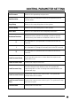
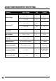
FUNCTION PARAMETER SETTING Content Input Range Unit Default 0.2 ~ 20.0 bar 16.0 10 ~ 300 psi 230 -9.9 ~ 9.9 bar 0.0 -99 ~ -99 psi 0 0 ~ 20 cycle 5 Min. Out Rate 30.00 ~ 70.00 % 50.00 Stop Rate 30.00 ~ 95.00 % 65.00 [Foward] [Backward] - Forward Low Current Alarm [Used] [Not Used] - Not Used Low Current Value 0.0 ~ 99.
FUNCTION PARAMETER SETTING Sensor Range To set-up the rated capacity of the pressure sensor utilized. Sensor Offset To correct the variation between the value of the pressure sensor and acutual pressure value. Auto Reset Refers to the number of times the system will reset once an alarm occurs. Min. Op. Rate Refers to the minimum output. Stop Rate Refers to the stop output. Motor Direction Direction of the motor. Low Curr. Alarm Refers to the Stop output. Low Curr.
VFD CONTROL PARAMETER SETTING Parameters Input Range Unit Default Max.Output Frequency 5.0 ~ 70 Hz 50.0 Max. Voltage Frequency 5.0 ~ 70 Hz 50.0 Max. Voltage 50 ~ 250 VAC 240 Mid-Point Frequency 5.0 ~ 70 Hz 25 Mid-Point Voltage 0 ~ 250 VAC 120 0.10 ~ 20.00 Hz 1.50 Min. Output Voltage 3.0 ~ 200 VAC 15 Acceleration Time 1.0 ~ 120 Sec. 3.0 Deceleration Time 1.0 ~ 120 Sec. 3.0 0: Ramp to Stop/ 1: Coast to Stop - 1 Min. Output Frequency Stop Mode IDM-1007M [0.5HP] [0.
INVERTER CONTROL PARAMETER Max. Output Frequency This parameter determines the inverters max. output frequency. Max. Voltage Frequency This value should be set according to the rated frequency of the motor. Mid-Point Frequency Refers to the mid-point frequency of the V/F curve. The V/F ratio between the min. frequency and mid-point frequency can be determined. Mid-Point Voltage Refers to the mid-point voltage of any V/F curve. The V/F ratio between the min.
SYSTEM PARAMETER SETTING 12 Parameters Input Range Default Power Outage Restart [System Stop] [System Run] [Backup State] Backup State Language [Korean] [English] English Password (0000: Not Used) 0000 ~ 9999 0000 Test Code 0000 ~ 9999 0000 INTELLIMASTER Variable Speed Controller User Manual
ALARM Display Alarm Type Corrective Action Communication Fail Check the connection status between the master and slave pumps. Sensor Open Check if the sensor connection has been properly performed. Replace the sensor if the error still occurs after checking the connection. Sen.Short Sensor Short Check if the sensor connection has been properly performed. Replace the sensor if the error still occurs after checking the connection. High Pres.
1-21 Monash Drive, Dandenong South, VIC 3175 Australia | 1300 137 344 | pentair.com.au Disclaimer: Pentair reserves the right to change product specifications and products details. All product images are for reference purposes only and may not represent actual and/or current product. ©2022 Pentair. All rights reserved. L100367 - 0822 Information contained here-in remains the property of Pentair under Australian copyright law.