
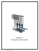
Installation Guide

6
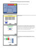
BASIC DESCRIPTION AND OPERATION OF BOOSTER CONTROLLER
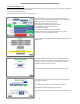
Equipment Maintenance Alarm based on Hours of Operation and
Starts. To disable Alarms, enter ‐1 at Default.
Maintenance Alarms indicated and Reset on Home screen.
Maintenance grouped:
First line ‐ Number of operations/hours. Zeros upon Alarm reset.
Second line ‐ Default setting for Maintenance Alarm.
Third line ‐ Total accumulation. Can't be modified.
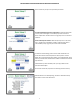
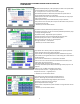
An alarm is activated when First line's number equals or exceeds
Alarm Default. A marker will appear at the default when alarm
activates on the Maintenance Alarm screen. A Maintenance Alarm
will be flashing on Home Screen. If alarm in Alarm Group is
acknowledged, then Maintenance Alarm will stop flashing and
number (counts) will stay active. If alarm is reset, then the number
or counts will be reset to zero. Default will stay the same and Total
will continue to accumulate throughout the life of PLC.
Defaults can be modified.
Alarm records can be retrieved in Fault and Alarm History.
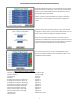
COM – Optional functions: SD Card and Ethernet with Web Server:
SD Card: Can copy Settings and Values from PLC to SD Card or saved
Values on SD Card to PLC.
Webserver: Ethernet Web Server, SD Card included and must be in
installed in the Controller for operation.
Remote Operation ‐ Enable/Disable via Modbus Control.
Ethernet, Port 3, if available: Modbus IP Bridge Access.
PLC Name ‐ If Network requires.
RS 485 ID ‐ Modbus Bridge Access.
Active Communication ‐ Flashing Green = Active.
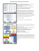
Real-time Drive information and Controls. HMI Drive controls allow
basic drive operation without using the Local Control Panel at VFD.
Drive screens monitors basic Drive Parameters, Speed in Hz, and VFD
On/Off. VFD must be in Auto Mode for this screen operation. On
Auto Test and on Transducer failure this screen will go into Manual
Control.