
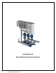
Installation Guide

5
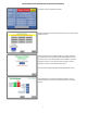
BASIC DESCRIPTION AND OPERATION OF BOOSTER CONTROLLER
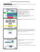
DC signal supplied by controller. Inputs selectable as: Unused, Alarm,
Fault, Fault Reset or For Relay Out. Input 1 may be selected to Stop
Pumps. 4 Inputs standard, additional 4 can be added as an option.
See IntelliBoost Electrical Drawing
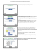
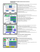
If Alarm is selected, press Alarm Button to configure. Input Alarm
Configuration screen will display. See Input Alarm Configuration
screen.
Once alarm has been pressed from previous screen, continue with
configuration. Setup Input 1,2,3,4 will allow multiple alarms to cause
a fault. Inputs 5‐8 Alarm Configuration allowed, if available.
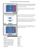
Alarms are recorded. Number of Alarms is a set value not to be
exceeded. If exceeded within a set time period, a Fault will occur and
system will stop operating. Fault restart requires Operator assistance.
Fault must be cleared or disabled for continued operation.
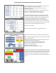
The output relays are form C contacts rated 240Vac 6A. 4 Relay
Outputs are standard, additional 4 can be added as an option. See
IntelliBoost Electrical Drawing
Relay Outputs can choose to indicate:
System On Auto Flow Alarm High
System On Manual Flow Fault High
Pump Running All Alarms
VFD Alarm All Faults
Discharge Pressure System Alarm Low Digital In 1
Discharge Pressure System Fault Low Digital In 2
Discharge Pressure System Alarm High Digital In 3
Discharge Pressure System Fault High Digital In 4
Suction Pressure System Alarm Low Digital In 5
Suction Pressure System Fault Low Digital In 6
Suction pressure System Alarm High Digital In 7
Suction pressure System Fault High Digital In 8
Flow Alarm Low Maintenance Alarm
Flow Fault Low