
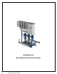
Installation Guide

3
BASIC DESCRIPTION AND OPERATION OF BOOSTER CONTROLLER
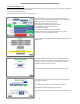
Normal Operation (Auto On ‐ VFD)
The Pump Controller receives a system pressure signal from the Discharge Pressure Transducer. The signal is compared to
the Set point and the pump(s) speed is adjusted.
Set point: Desired system pressure.
Minimum Set point: Desired minimum system pressure.
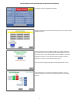
Home: Default Screen on power‐up. Shows real-time system
operation, status, settings and hardware. Horn & Lt Enable/Disable
and active Alarms can be viewed and reset
PLC screen operates with touch response.
Flashing Green = Optional Active Communication
RS = Ramp Speed, limits speed when Red
NF = No Flow, when Red
OC = Overcurrent/Minimum Suction, when Red
Remote Active displays when Remote operation is turned on.
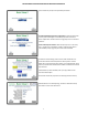
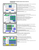
Continue to Setup: Touch Menu on screen
Menu = the base of navigation. May be Password Protected, refer to
Basic Setup 4.
If activated, Password Entry Basic screen will display when Menu
button touched. When correct Pin is entered, Menu screen will
display. If incorrect, returns to screen with message “Incorrect
Password”. Reenter correct Pin or ESC.
See Password Disable/Enable Set Password/Pin Number screen.
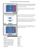
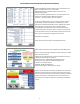
Basic Setup screens need to be completed by Factory and/or End
User before operation.
To set Time, Date and Year ‐ Touch SET, enter information.
Set Discharge and Minimum Discharge Set points.
Minimum Discharge Set point ‐ Minimum system allowable pressure