
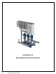
Installation Guide
1
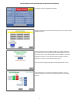
Bas i c O p e r a ti o n of the P u m p Co n t r o l ler
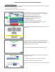
Multiple Pump Controllers -maximum (4) VFD's:
The controller will have a power OFF/ON selector switch to power up system. The normal operation of the
controller as well as the staging of the pumps is controlled by an independent processor. The VFD(s) act as
"signal follower" and do not independently control the speed of the pumps in "Auto On" mode. For initial
setup and in the event of a system failure, the VFD(s) can run the pumps in "Hand On" control at a user
selected fixed speed, ignoring all signals from the pump controller.
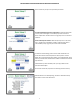
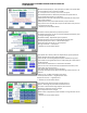
VFD Operation:
2‐4 drives operate in the same manner. Hand On, Off, Auto On and Reset is the basic operations for the Local
Control Panel. "Hand On" selection required for independent drive manual operation. Off will turn off VFD,
stopping pump rotation.
Auto On is selected when PLC is ready for testing and operation. Reset in case of VFD
fault, refer to operation
manual.
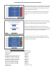
VFD Parameters and Communication Settings:
VFD parameters set as described below should be entered when VFD is in the Off position. PLC and VFD are
master slave configured using Mod Bus RTU communication. Loss of communication will stop drive after
Timeout. Each drive shares same parameter set except where drive name is required (Drive1 = 2, Drive2 = 3,
Drive3 = 4, Drive4 = 5). A Master Local Control Panel, LCP, is used to Copy and Download parameters from VFD
to VFD.
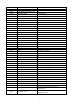
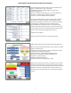
Parameters:
Refer to following page for Parameter Settings.