
Installation Guide


BASIC DESCRIPTION AND OPERATION OF BOOSTER
CONTROLLER
10
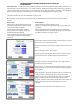
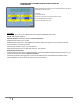
Bypass Password Protection. Basic and Advanced Passwords may be
accessed from Home screen.
To Access:
Go to Home Screen
Touch the Time once (in right‐hand upper corner)
Touch PENTAIR logo three times
Touch Discharge PSI text once
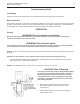
Controller:
Description: 16”h x 12”w x 8”d, NEMA 4 Enclosure (Optional NEMA 4X Clear Cover)
Power: 100‐240 VAC 50/60 Hz
Operator Controls:
Audible/Visual Alarm
Control Connections:
RS485 Communication Port 1 to VFDs
RS485 Communication Port 2, See Modbus Slave Address Table
Discharge Pressure Transducer (4‐20 mA)
Suction Pressure Transducer (4‐20 mA)
External Fault and Alarm inputs, (4) ‐ User defined
Relay Outputs (6 amp, form ‘C’) fault and alarm, (4) ‐ User defined
Additional I/O Connections:
External Fault and Alarm Inputs, maximum (8 total) – User defined Additional Relay Outputs (6 amp, form ‘C’),
maximum (8 total) ‐ User defined
Additional Options:
SD Card for application settings (Copy To and From SD Card)
Ethernet, See Modbus Slave Address Table
Ethernet Webserver ‐ Home Screen and Maintenance Alarm Screens