IntelliBoost 3.
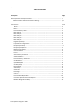
. TABLE OF CONTENTS Description Page Basic Operation of Pump Controller…………....……………………………………………………………… 1 VFD Parameters and Communication Setting…....…...…..……………………………………….. 1,2 PLC Screens 3‐10 Home …………………………….………………...…………………………………………………………………… 3 Menu ….……..……………………..………….…...…….…………………………………………………………… 3 Password Entry ‐ Basic …....……..……..……...……………………………………………………………… 3 Basic Setup 1 ..………..……….……..…….….......……………………………………………………………… 3 Basic Setup 2 …..……..……….……..…….….......
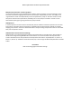
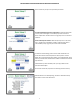
B a s i c O p e r a t i o n of the P u m p C o n t r o l ler Multiple Pump Controllers -maximum (4) VFD's: The controller will have a power OFF/ON selector switch to power up system. The normal operation of the controller as well as the staging of the pumps is controlled by an independent processor. The VFD(s) act as "signal follower" and do not independently control the speed of the pumps in "Auto On" mode.
PARAMETER 0‐01 0‐02 0‐03 1‐03 1‐23 1‐24 1‐25 3‐03 3‐41 3‐42 4‐14 4‐19 4‐12 5‐12 8‐01 8‐03 8‐04 8‐10 8‐30 8‐31 8‐32 8‐33 8‐42 DESIGNATION Language Motor Speed Units, RPM or Hz Regional Settings Torque Characteristics Motor Frequency Motor Current Motor Speed Maximum Reference Ramp Up Time Ramp Down Time Motor High Speed Limit Maximum Output Frequency Motor Speed Low Limit Terminal 27 Control Site Control Time Out Control Time Out Function Control Word Profile Protocol Addresses FC Port Baud Rate Parity PCD
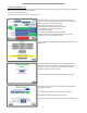
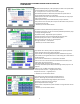
BASIC DESCRIPTION AND OPERATION OF BOOSTER CONTROLLER Normal Operation (Auto On ‐ VFD) The Pump Controller receives a system pressure signal from the Discharge Pressure Transducer. The signal is compared to the Set point and the pump(s) speed is adjusted. Set point: Desired system pressure. Minimum Set point: Desired minimum system pressure. Home: Default Screen on power‐up. Shows real-time system operation, status, settings and hardware.
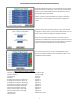
BASIC DESCRIPTION AND OPERATION OF BOOSTER CONTROLLER Select number of pumps to be operated by Controller. Timed Pump Rotation by Hours of Operation: Lead pump will rotate on every start and changes to next lead pump when continuous Hours of Operation Timed is timed out. Lag pump turns on and off as called for. Same Lead Pump for all Starts: Same Lead pump turns on for every start. If Lead pump is disabled in anyway, Lead Pump will shift to next available pump. Lag pump turns on and off as needed.
BASIC DESCRIPTION AND OPERATION OF BOOSTER CONTROLLER DC signal supplied by controller. Inputs selectable as: Unused, Alarm, Fault, Fault Reset or For Relay Out. Input 1 may be selected to Stop Pumps. 4 Inputs standard, additional 4 can be added as an option. See IntelliBoost Electrical Drawing If Alarm is selected, press Alarm Button to configure. Input Alarm Configuration screen will display. See Input Alarm Configuration screen.
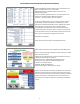
BASIC DESCRIPTION AND OPERATION OF BOOSTER CONTROLLER Equipment Maintenance Alarm based on Hours of Operation and Starts. To disable Alarms, enter ‐1 at Default. Maintenance Alarms indicated and Reset on Home screen. Maintenance grouped: First line ‐ Number of operations/hours. Zeros upon Alarm reset. Second line ‐ Default setting for Maintenance Alarm. Third line ‐ Total accumulation. Can't be modified. An alarm is activated when First line's number equals or exceeds Alarm Default.
BASIC DESCRIPTION AND OPERATION OF BOOSTER CONTROLLER Complete history of all Alarms and Faults. Advanced Menu may be Password Protected, refer to Password Entry Advanced screen. If Password Protection for Advanced Menu is enabled, Password Entry Advanced screen will display when Advanced Menu button touched. When correct Password/Pin is entered Menu screen will display. If incorrect, returns to screen with message “Incorrect Password”. Reenter correct Password/Pin or ESC.
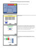
BASIC DESCRIPTION AND OPERATION OF BOOSTER CONTROLLER HMI Manual Max Speed (Hz) ‐ Max speed (Hz) the VFD’s can operate when set used as Manual Control operation via HMI. Note - VFD keypad must be in Auto On for manual control through HMI. Max and Min Speed VFDs ‐ Maximum speed VFD can operate when in Auto On mode and Controller is in operation. Reduce Speed on No Flow: If ON and no flow is detected, will stop pumps under normal operation.
BASIC DESCRIPTION AND OPERATION OF BOOSTER CONTROLLER Auto-Commission- To commission your Intelliboost system you must have the Main Discharge Isolation Valve turned in the off position to ensure the booster is in a “no flow” condition. (Suction Main Isolation Valve remains open). No Flow Test or No Flow Adjust, required a means to ensure no flow can occur. Remote Operation, if available, must be Disabled.
BASIC DESCRIPTION AND OPERATION OF BOOSTER CONTROLLER Bypass Password Protection. Basic and Advanced Passwords may be accessed from Home screen.
IntelliBoost System for PLC 570 Modbus Slave Address Table Booster Communication: Ethernet Modbus TCP IP Slave, Port 502 Data: All packed values stored as most significant byte . . . , Subnet Mask: . . . Gateway: . . .
11 Intelliboost™ Water Booster System Basic Operation Manual Troubleshooting Guide Field Wiring All wiring connections and wiring sizes must meet National Electrical Code and local requirements. Motor Protection See the motor nameplate for electrical connection/wiring diagram. Aurora® pumps must be used with the proper size and type of motor starter to ensure protection against damage from low voltage, phase failure, current imbalances, and overloads.
12 Intelliboost™ Water Booster System Basic Operation Manual NOTICE: Please see to “Starting” before proceeding any further. Operation of open systems with the liquid level below the top of the pump: NOTICE: The suction pipe requires a check valve or isolation valve. 1. Close to discharge isolation valve. 2. Remove the vented priming plug. 3. Pour liquid through the priming port until the suction pipe and the pump are completely filled with liquid. 4.
13 Intelliboost™ Water Booster System Basic Operation Manual WARNING! If motor is nameplated for hazardous locations, do not run motor without all of the grease or drain plugs installed.
14 Intelliboost™ Water Booster System Basic Operation Manual WARNING! Risk of electrical shock and possible unexpected starts. Disconnect all power to the pump before servicing or working on pump. Make sure that power is locked out and that pump cannot be accidentally started. Problem Cause 1. Motor does not run when started A. Power failure B. Fuses blown C. Motor starter overload has tripped out D. Main contacts in motor starter are not making contact or the coil is faulty. F. Motor is defective 2.
Intelliboost™ Water Booster System Basic Operation Manual 15 NOTICE: The suction pipe requires a check valve or isolation valve. 1. Close to discharge isolation valve. NOTICE: Please see “Starting” before proceeding any further. CHECKING DIRECTION OF ROTATION NOTICE: Do not disconnect the motor from the shaft to check the direction of rotation. If you remove the coupling, then you must adjust the shaft position when you reinstall it. This must be done before starting the pump.
16 Intelliboost™ Water Booster System Basic Operation Manual 4. Check the tightness of connections. a. Loose power connections can cause extra heating and/or arcing. The heating reduces efficiency and can actually melt down connectors. The arcing can cause intermittent currents and electrical noise. These can disrupt the operation of the drive. b. Loose or corroded ground connections can cause electrical noise problems. All of the VLT drives have some degree of electrical noise filtering.
Danfoss Drive Preventive Maintenance Instruction 1. PM Checklist Check box Preventative Maintenance Step Vacuum dust and dirt from heat sink fins Clean or replace as conditions require intake air filters (125 Hp constant torque models, 150 Hp variable torque models and larger have filters located behind the intake louver panels) Check ventilation fans for proper operation and clean as needed. Confirm VFD’s ventilation clearances have not been obstructed Check electrical connections and re-torque as needed.
b. Because the loading of the air filters can vary dramatically from one installation to another, it is important to initially check the air filters frequently to establish the required inspection interval. 4. Check the tightness of connections. a. Loose power connections can cause extra heating and/or arcing. The heating reduces efficiency and can actually melt down connectors. The arcing can cause intermittent currents and electrical noise. These can disrupt the operation of the drive. b.
d. With power removed from the drive, a physical inspection of the capacitors should not show any deformation of the cases of the capacitors or liquid leaking from them. e. Low voltage capacitor testers are of no use in checking DC bus capacitors. The main concern is to ensure that the capacitors don’t have excessive leakage current when the DC bus voltage is applied to it. This cannot be tested at a low voltage. f.
July 1, 2002 Aurora Pump 800 Airport Road North Aurora, IL 60542 Phone: 630-859-7000 Fax: 630-859-7034 APPLI CATI ONS ENGI NEERI NG NEWSLETTER Bearing Lubrication Instructions for 300 Series End Suction Frame Mounted Pumps Greas e lubrication is s tandard for the Aurora End Suction F rame Mounted Pumps . Regreaseable bearings will require lubrication replacement and this can be accomplis hed by us ing the lubrication fitting at each bearing.
CAUTION Overgr%~~slng beaFings can auw prematureh r l n g andlor motor failum The amount of grease added should be carefully controlled. NOTE If lubrication instruetlons are shown on the motor nameplate, they wlll supersede th1o generat Instruction. SEVERE SERVICE: Greater than 16 hours of operation per day.
Field Wiring 2. Slowly open the isolation valve in the suction pipe until a steady stream of liquid runs out the vent in the priming port. 3. Tighten needle valve to 25 inch-pounds. Completely open isolation valves. NOTICE: Please turn to Starting before proceeding any further. Operation of open systems with the liquid level below the top of the pump: NOTICE: The suction pipe requires a check valve or isolation valve. 1. Close the discharge isolation valve. 2. Remove the vented priming plug. 3.
Troubleshooting Risk of electrical shock and possible unexpected starts. Disconnect all power to the pump before servicing or working on pump. Make sure that power is locked out and that pump cannot be accidentally started. Problem Cause A. Power failure # 'VTFT CMPXO 1. Motor does not run when started C. Motor starter overload has tripped out D. Main contacts in motor starter are not making contact or the coil is faulty E. Control circuit fuses are defective ' .PUPS JT EFGFDUJWF A.
G2 ELECTRICAL TERMINATIONS AND WIRING G2 ELECTRICAL TERMINATIONS AND WIRING DEUTSCH DT SERIES DT04-3P 4-20mA Output* V– V– V+ Mating Cable Color Black White Red 3 (A) 2 (C) 1 (B) Wire Length 3 Mating Cable Color Red Black White 2 DIN 43650 FORM C (EN 175301-803-C) ELECTRICAL TERMINATION (DC), (N1), (N2), (N3), (N9) 1 Mates to Hirschmann P/N: GSSNR 300, Ashcroft P/N 300A126-01 * Use either V- termination on G2 with 4-20mA output Pin No.
• When disconnecting, remove the ground LAST! Note: The shield and drain wire in the cable (if supplied) is not connected to the transducer body, and is not a suitable ground. DESCRIPTION The Ashcroft Model G2 and T2 pressure transducers are high performance instruments intended for use in industrial applications where the process media is compatible with the 17-4PH stainless steel sensor material and the 304 SS process connection.
WARRANTY Seller warrants equipment (and its component parts) of its own manufacture against defects in materials and workmanship under normal use and service for one (1) year from the date of installation or start-up, or for eighteen (18) months after the date of shipment, whichever occurs first.