
User's Manual


68
EasyTouch Wireless Control Panel Installation and User’s Guide
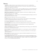
4. Lower down the hinged control panel to access the EasyTouch motherboard.
5. Route the four conductor transceiver connection cable into the lower plastic grommet, up through the
low voltage raceway to the EasyTouch load center motherboard.
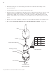
6. Strip back the cable conductors ¼ inch. Insert the wires into the screw terminals (provided in the kit).
Secure the wires with the screws. Make sure to match the color-coding of the wires:
GND = Black, Green = -DT, Yellow = +DT, and Red = +15
7. Insert the screw terminal connector onto the COM-PORT (J20) connector on the motherboard.
Note: Multiple wires may be inserted into a single screw terminal.
8. Close the control panel into its original position and secure it with the two access screws.
9. Install the high voltage cover panel and secure it with the two retaining screws.
10. Close the EasyTouch load center front door. Fasten the two spring latches.
11. Switch the power on to the EasyTouch load center.
Low voltage
Raceway
Control panel
motherboard
COM PORT
(J20)
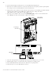
Indoor Control Panel
IntelliChlor
IntelliFlo
RF Transceiver
EasyTouch Motherboard