I N S T A L L A T I O N Endura® EW5001 Wireless Access Point/Bridge C2681M (2/08)
Contents Regulatory Notices . . . . . . . . . . . . . . . . . . . . . . . . . . . . . . . . . . . . . . . . . . . . . . . . . . . . . . . . . . . . . . . . . . . . . . . . . . . . . . . . . . . . . . . . . . . . . . . . . . . . 4 Exposure to Radio Frequency Fields . . . . . . . . . . . . . . . . . . . . . . . . . . . . . . . . . . . . . . . . . . . . . . . . . . . . . . . . . . . . . . . . . . . . . . . . . . . . . . . . . . . 4 Video Quality Caution . . . . . . . . . . . . . . . . . . . . . . . . . . . . .
List of Illustrations 1 2 3 4 5 6 7 8 9 10 11 12 13 14 15 16 17 18 19 20 21 Package Contents . . . . . . . . . . . . . . . . . . . . . . . . . . . . . . . . . . . . . . . . . . . . . . . . . . . . . . . . . . . . . . . . . . . . . . . . . . . . . . . . . . . . . . . . . . . . . . . . . 7 Sample EW5001 Access Point Application Scenario. . . . . . . . . . . . . . . . . . . . . . . . . . . . . . . . . . . . . . . . . . . . . . . . . . . . . . . . . . . . . . . . . . . . . .
Regulatory Notices This device complies with Part 15 of the FCC Rules. Operation is subject to the following two conditions: (1) this device may not cause harmful interference, and (2) this device must accept any interference received, including interference that may cause undesired operation. RADIO AND TELEVISION INTERFERENCE This equipment has been tested and found to comply with the limits of a Class A digital device, pursuant to Part 15 of the FCC Rules.
Description The EW5001 is a high-performance, single-radio wireless unit that can be configured as either an access point or a bridge. Access point: The EW5001 provides a wireless link between a cluster of EW5301T wireless video encoders and an Endura® network in a point-to-multipoint configuration. It serves as a proprietary wireless network router (refer to Figure 2 on page 8). The EW5001 receives MPEG-4 video streams from EW5301T wireless video encoders.
Before You Begin Endura is a network system that requires a continuous amount of bandwidth to transmit true, live video. Therefore, always include your network administrator when planning and installing Endura components.
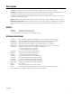
PACKAGE CONTENTS The following diagram shows the contents of the box. J-BOX 1 EA. INSTALLATION MANUALS (2 EA.), CONFIGURATION MANUAL, SAFETY INSTRUCTIONS WEATHERPROOF NETWORK CONNECTOR 1 EA. POWER CONNECTOR AND CABLE 1 EA. EW5001 1 EA. Figure 1.
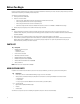
APPLICATION SCENARIOS Figure 2 shows the EW5001 used as an access point for multiple EW5301T video encoders in a sample application scenario. NETWORK EW5001 ACCESS POINT CAMERA CAMERA CAMERA EW5301T UNITS Figure 2. Sample EW5001 Access Point Application Scenario IMPORTANT NOTE. PLEASE READ. The network implementation in this document is shown as a general representation only and is not intended to show detailed network topologies.
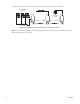
Figure 3 shows the EW5001 used as a wireless bridge between an Endura network and an EW5002 with a cluster of EW5301T video encoders. NETWORK EW5002 EW5001 BRIDGE BACKHAUL ACCESS POINT CAMERA CAMERA CAMERA EW5301T UNITS Figure 3.
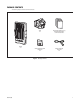
Figure 4 shows the EW5001 used as a wireless bridge between an Endura network and an Endura-enabled IP-type device. IP-TYPE CAMERA SYSTEMS NETWORK EW5001 EW5002 EW5001 IP-TYPE CAMERA SYSTEM BACKHAUL BRIDGE BRIDGE BACKHAUL SWITCH Figure 4. Sample EW5001 Wireless Bridge with IP-Type Devices Application Scenario NOTE: This scenario can only be configured by an Endura-certified technician. Refer to the Endura Wireless Device Advanced Configuration Interface manual (C3615M) for more information.
PRODUCT SERIAL NUMBER LABEL PLACEMENT Product serial number labels help Pelco Product Support identify your system and its factory configuration in case the EW5001 or its components require service. A label citing your product’s serial number is attached to the rear panel of the EW5001. Because the label will be covered by the J-box (supplied), two additional labels are provided. These additional labels also list the media access control (MAC) or network adapter address for the unit.
Site Preparation Before you install the EW5001, complete the following items: • Select a site for the EW5001. • Install a mount for the EW5001. • Wire the site for power and network access. The EW5001 supports Power-over-Ethernet (PoE). • Install the antenna. • Optional: Configure the network and wireless settings for the EW5001 on a workbench.
POWER AND NETWORK WIRING The EW5001 supports two methods for supplying power and network access to the unit: separate power and network cables or a single network cable using Power-over-Ethernet (PoE) technology. The following sections describe both methods. SEPARATE POWER AND NETWORK CABLES Figure 6 shows how to connect separate power and network cables to the EW5001.
To install the power cable (refer to Figure 6 on page 13): 1. Run power lines from the power supply to the mount site (refer to the power specifications at the start of this section). 2. Connect the power lines from the power supply to the supplied power cable, as indicated: Wire Color DC AC White DC+ AC+ Black Ground AC- NOTES: • • • • • Be sure to use environmentally-rated connectors when connecting power to the EW5001. Otherwise, unit reliability may suffer.
To install the network cable (refer to Figure 6 on page 13): 1. Run the network cable from a network switch inside the building to the mount site. The equipment must support Gigabit Ethernet operation. NOTE: If you use a junction box or patch panel, make sure the connection is protected from the weather. 2.
POWER-OVER-ETHERNET (POE) Power-over-Ethernet (PoE) lets you supply both power and network connectivity over a single cable. This simplifies installation and decreases the potential for unit failure. The EW5001 supports PoE from either a PoE injector or a PoE-enabled network switch. The equipment must support Gigabit Ethernet and supply 15.4 W at 48 VDC. Unit power consumption is 9.7 W (16.2 VA). Approved gigabit PoE injectors are available from Pelco.
To install PoE for the EW5001 (refer to Figure 8): 1. Install the PoE equipment (refer to the equipment documentation). 2. Run the network cable from the PoE equipment to the mount site. The equipment must support Gigabit Ethernet operation. NOTE: If you use a junction box or patch panel, make sure the connection is protected from the weather. 3.
ANTENNA INSTALLATION Pelco offers a planar antenna with integrated mount (EW-ANTP-2-9 or EW-ANTP-5-8) for use with the EW5001. These are the only antennas that can be mounted directly to the EW5001. Any other antenna must be mounted separately. Before installing either an integrated antenna or a separate antenna, review the following considerations: • Make sure the elevation (height) and azimuth (horizontal angle) match at both wireless antenna sites.
Unit Installation To install the EW5001: NOTE: If installing a separate antenna, skip to step 2 on page 20. 1. Attach the integrated antenna and antenna cable to the EW5001. NOTES: • a. It is easier to attach the integrated antenna to the unit on the ground before carrying it up to the mount. • Do not rest the device on the integrated antenna; the antenna mount cannot support the weight of the device. Attach the integrated antenna to the EW5001 (refer to Figure 10).
2. Install the mount (refer to the mount documentation for more information). 3. Orient the J-box so that the arrows and the word “UP” are pointed up (refer to Figure 12). Figure 12. J-Box Orientation 4. Secure the J-box to the mount (refer to Figure 13). NUT LOCK WASHER WASHER Figure 13. Installing the J-Box (EWM shown) NOTES: • • 20 The nuts, washers, and lock washers shown in Figure 13 are for illustration only. They are not supplied with the EW5001.
5. Identify the best route for the power and network cables into the J-box (refer to Figure 14). WEATHERPROOF NETWORK CABLE (NOT SUPPLIED) POWER (FROM SOURCE) Figure 14. Routing Power and Network Cables 6. To use the top or bottom opening for cables: Remove the plug from the appropriate opening in the J-box (refer to Figure 15). Use a 7/16-inch wrench. PLUG Figure 15. Removing an Auxiliary Opening Plug 7.
8. Hang the hinge of the EW5001 onto the hinge bolts in the J-box (refer to Figure 16). Figure 16. Attaching the EW5001 to the J-Box 9. Tighten the hinge bolts to secure the EW5001 to the J-box.
10. Connect all cables (refer to Figure 17): NOTE: Be sure to fully seat each connector. Otherwise, environmental protection may fail, causing the unit to fail. WEATHERPROOF NETWORK CONNECTOR (SUPPLIED) WEATHERPROOF NETWORK CABLE (NOT SUPPLIED) POWER CABLE (SUPPLIED) Figure 17. Connecting Cables to the EW5001 a. b. If installing a power cable: Connect the power cable connector. (1) Remove the protective cover from the power connector on the rear panel.
DISCONNECTING AN ANTENNA CABLE The antenna cable connector is locking. To disconnect it, first pull the sleeve away from the device and hold it (refer to Figure 18). Then pull the connector from the device. SLEEVE Figure 18. Disconnecting an Antenna Cable Connector OPENING THE J-BOX The latch that secures the EW5001 includes a safety release. To open the J-box, refer to Figure 19 and perform the following steps: 1. Press and hold the safety release. 2. Release the latch. 3. Open the J-box.
Operation INDICATORS The EW5001 has a set of six indicators on its rear panel (refer to Figure 20). These indicators show unit status during startup and normal operation. STATUS INDICATORS Figure 20. EW5001 Status Indicators INDICATORS DURING STARTUP During the startup sequence, the unit steps through a number of phases. The color of the MODE indicator shows the status of each phase: • Green: The phase was completed successfully. • Amber: The phase is in process.
INDICATORS DURING OPERATION During operation, the indicators show unit status as well as status changes (refer to Table D). Table D. Indicators During Operation Status Change MODE 1 2 3 4 5 Unit connected to SM5000 and operating normally. Green On On Off On On Unit lost connection to SM5000 on Endura network. Amber On On Off On Blinking Endura network did not renew unit network address. Amber On On Off Blinking Off Bridge: Unit lost connection to peer bridge.
3. Point the antenna on the EW5001 toward the antenna on the other Endura wireless device. 4. Set the scale on the DVM for 0 VDC (zero VDC) to 6 VDC. 5. Uncap the RSSI connector on the EW5001 (refer to Figure 21). NOTE: The cap is attached to the EW5001; you will reinstall it later to protect the unit from weather damage. DIGITAL VOLTMETER BNC CABLE RSSI CONNECTOR CAP BNC ADAPTER Figure 21. Connecting a DVM to the EW5001 6. Connect the DVM and a BNC adapter to the RSSI connector on the EW5001. 7.
Troubleshooting If the following instructions fail to solve your problem, contact Pelco Product Support at 1-800-289-9100 (USA and Canada) or 1-559-292-1981 (international) for assistance. Access the properties windows for the EW5001 wireless access point/bridge on the Endura workstation; refer to the Endura WS5000 Advanced System Software Operation manual (C1624M).
Specifications MODEL NUMBER EW5001-2 Wireless access point or bridge; 2.4 GHz EW5001-5 Wireless access point or bridge; 5.8 GHz SUPPLIED ACCESSORIES Power Cable with Connector 1 Weatherproof Network Connector 1 SYSTEM Operating System Linux® User Interface Remote operation from Endura workstation or VCD5000 INDICATORS MODE Green, amber, red 1 through 5 Green RADIO FREQUENCY Wireless Radio Standards 802.11a/802.11g Modulation OFDM Transmitting Frequency 2.4 GHz* 5.8 GHz 2.412 to 2.
POWER Power Consumption 9.7 W, 33 BTU/H Power Input 12 VDC ±10% 24 VAC ±10% 48 VDC (PoE) (802.3af-compliant) ENVIRONMENTAL Operating Temperature -30° to 122°F (-34° to 50°C) Storage Temperature -40° to 149°F (-40° to 65°C) Operating Humidity 20% to 95%, noncondensing Operating Altitude -50 ft to 10,000 ft (-16 m to 3,048 m) PHYSICAL Construction Cast aluminum Finish White powder coat Dimension (Without Antenna) 8.76" D x 8.66" W x 14.49" H (22.25 x 22.00 x 36.
PRODUCT WARRANTY AND RETURN INFORMATION WARRANTY Pelco will repair or replace, without charge, any merchandise proved defective in material or workmanship for a period of one year after the date of shipment. Exceptions to this warranty are as noted below: • Five years on fiber optic products and TW3000 Series unshielded twisted pair (UTP) transmission products. • Three years on Spectra® IV products. • Three years on Genex® Series products (multiplexers, server, and keyboard).
Worldwide Headquarters 3500 Pelco Way Clovis, California 93612 USA USA & Canada Tel: 800/289-9100 Fax: 800/289-9150 International Tel: 1-559/292-1981 Fax: 1-559/348-1120 www.pelco.