
Installation Manual

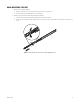
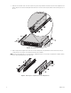
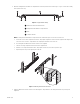
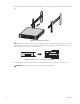
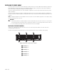
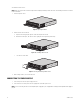
Table Of Contents

C4687M-C (7/13) 17
5. Mount the sliding brackets with attached L-shaped brackets to the rack, back to back as shown in Figure 11. Figure 10 shows the assembly
items required for this step.
Figure 10. Support Rail Assembly
NOTE: The sliding brackets with attached L-shaped brackets are identical and may be used on either side of the rack.
a. Position the ear of the front L-shaped bracket and an L-shaped plate nut against the inside front of the equipment rack. Align the two
center holes in the ear of the L-shaped bracket and L-shaped plate nut with the holes in the rack.
b. Insert and tighten two M5 x 8L-H2.5 round head nickel screws (supplied).
c. Slide the rear-facing L-shaped bracket to the back of the equipment rack.
d. Attach the rear L-shaped bracket and another L-shaped plate nut to the rack, as described in previous steps.
e. Repeat the previous steps for the opposing side of the rack.
Figure 11. Attaching the Brackets to the Rack
6. Tighten the M4 x 6L-H2.5 round head nickel screws attaching the L-shaped brackets to the sliding brackets that were previously left
untightened.
ì
M5 x 8L-H2.5 Round Head Nickel Screws
î
Sliding Bracket with Attached L-shaped Brackets
ï
Rack
ñ
L-Shaped Plate Nut