I N S T A L L A T I O N Endura SM5200 System Manager ® C4687M-C (7/13)
Contents Important Notices . . . . . . . . . . . . . . . . . . . . . . . . . . . . . . . . . . . . . . . . . . . . . . . . . . . . . . . . . . . . . . . . . . . . . . . . . . . . . . . . . . . . . . . . . . . . . . . . . . . . . 5 Legal Notice . . . . . . . . . . . . . . . . . . . . . . . . . . . . . . . . . . . . . . . . . . . . . . . . . . . . . . . . . . . . . . . . . . . . . . . . . . . . . . . . . . . . . . . . . . . . . . . . . . . . . 5 Regulatory Notices . . . . . . . . . . . . . . . . . . . . . . .
List of Illustrations 1 2 3 4 5 6 7 8 9 10 11 12 13 14 15 16 17 18 19 20 4 Major Package Components. . . . . . . . . . . . . . . . . . . . . . . . . . . . . . . . . . . . . . . . . . . . . . . . . . . . . . . . . . . . . . . . . . . . . . . . . . . . . . . . . . . . . . . . . 7 Accessory Pack . . . . . . . . . . . . . . . . . . . . . . . . . . . . . . . . . . . . . . . . . . . . . . . . . . . . . . . . . . . . . . . . . . . . . . . . . . . . . . . . . . . . . . . . . . . . . . . . . . . 8 Rack Mount Kit .
Important Notices LEGAL NOTICE SOME PELCO EQUIPMENT CONTAINS, AND THE SOFTWARE ENABLES, AUDIO/VISUAL AND RECORDING CAPABILITIES, THE IMPROPER USE OF WHICH MAY SUBJECT YOU TO CIVIL AND CRIMINAL PENALTIES. APPLICABLE LAWS REGARDING THE USE OF SUCH CAPABILITIES VARY BETWEEN JURISDICTIONS AND MAY REQUIRE, AMONG OTHER THINGS, EXPRESS WRITTEN CONSENT FROM RECORDED SUBJECTS.
Description The SM5200 system manager is a network appliance that serves as the system management component of the Endura® IP video management solution. This document provides instructions for mounting and installing your SM5200 hardware. Once you have installed the SM5200, you will have to perform some software configuration; for more information, refer to your SM5200 System Manager Configuration manual.
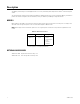
Before You Begin PACKAGE CONTENTS Figure 1. Major Package Components C4687M-C (7/13) ì SM5200 System Manager î SM5200-LIT Literature Kit: Includes product manual, product badge, and resource disc ï Accessory Pack ñ Hard Drive Pack (hard drives in carriers) NOTE: Number of hard drives depends on model. ó Rack Mount Kit (1 ea.
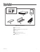
Figure 2. Accessory Pack 8 ì Power Cord (based on country designation (1 ea.) NOTE: Units shipped to China do not include power cords; a CCC approved power cord must be used to power this equipment when used in China. î USB Flash Drive (4GB) for System Migration (1 ea.) ï Bezel Keys (2 ea.) ñ Chassis Handles (2 ea.); Includes Phillips Screws for Installation. ó Rubber Feet (4 ea.
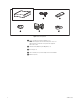
Figure 3. Rack Mount Kit C4687M-C (7/13) ì Chassis Brackets (2 ea.), Sliding Brackets (2 ea.) î L-Shaped Brackets (4 ea.) ï L-Shaped Plate Nuts (4 ea.) ñ M5 x 8L-H2.5 Round Head Nickel Screws (18 ea.), M4 x 6L-H2.5 Round Head Nickel Screws (18 ea.), 4.2 x 11 x 0.8 Nickel Washers (optional, 10 ea.
PRODUCT LABELS PRODUCT SERIAL NUMBER LABEL PLACEMENT Product serial number labels help identify your system and its factory configuration if your unit or its components should require service. Three labels citing your product’s serial number are attached to the unit. One label is attached to the upper-right corner of the rear of the unit. A second, smaller label is attached to the inside left of the bezel.
Product Overview REAR PANEL Figure 4. Rear Panel Layout ì Rear Chassis Fan î Power Receptacle ï Reserved (do not use) ñ Ethernet Ports • Network Port 1 (left is primary) • Network Port 2 (right is secondary) C4687M-C (7/13) ó Card Slots r Reserved (do not use) s Audio Out t Reserved (do not use) u USB 3.0 Ports ~í USB 2.
FRONT PANEL CONTROLS AND INDICATORS Figure 5. SM5200 Front Panel Layout (Bezel Open) Endura SM5200 Series Figure 6. Front Bezel Indicators (Bezel Closed) ì Unit Status • Green: The unit is functioning normally. • Flashing green: The unit is starting or shutting down. • Amber: The unit is nearing operational thresholds; maintenance is recommended. • Red: The unit is in an error condition (refer to Troubleshooting on page 24).
r Drive Status The drive status indicators report the operating status of each individual drive. • Flashing green: Read or write activity is occurring on the hard drive. • Solid red: A problem exists with the hard drive. • Flashing green/red: The hard drive is initializing. s C4687M-C (7/13) USB Ports The SM5200 includes one USB 2.0 port on the front panel and four ports on the rear panel (two USB 3.0 ports and two USB 2.0 ports).
Installation INSTALLING THE UNIT ON A DESKTOP WARNING: Do not place the unit on its side To install the unit on a desktop: 1. Secure rubber feet (included) to the unit’s bottom panel. 2. Position the unit to allow for cable and power cord clearance. RACK-MOUNTING REQUIREMENTS The unit occupies 2 rack units (RU) of vertical rack space (8.9 cm or 3.5 inches) in an industry standard 48 cm (19-inch) equipment rack. The hardware required for rack-mounting is included with the unit.
RACK-MOUNTING THE UNIT 1. Install the chassis handles (supplied): a. Align the screw holes on the chassis handles with holes near the front of the chassis. b. Insert and tighten the four Phillips flat head screws (supplied). 2. Remove the chassis brackets from the sliding brackets (both supplied): a. Slide both chassis brackets away from the sliding brackets until they lock in place. b. Release the chassis brackets from the sliding brackets.
3. Attach the chassis brackets to the sides of the unit (refer to Figure 8) using four M4 x 6L-H2.5 round head nickel screws (supplied) for each bracket. Align the chassis brackets starting with the threaded hole closest to the unit’s front panel, with the slotted ends facing the rear of the unit. Figure 8. Attaching the Chassis Brackets 4. Attach L-shaped brackets (supplied) to the front and rear of both sliding brackets using two M4 x 6L-H2.5 round head nickel screws per L-shaped bracket.
5. Mount the sliding brackets with attached L-shaped brackets to the rack, back to back as shown in Figure 11. Figure 10 shows the assembly items required for this step. Figure 10. Support Rail Assembly ì M5 x 8L-H2.5 Round Head Nickel Screws î Sliding Bracket with Attached L-shaped Brackets ï Rack ñ L-Shaped Plate Nut NOTE: The sliding brackets with attached L-shaped brackets are identical and may be used on either side of the rack. a.
7. Slide the SM5200 with attached chassis brackets into the sliding brackets. This step may require two people to lift and slide the unit into place. Figure 12. Installing the Unit in the Rack NOTE: Align the chassis brackets with the first slot on the sliding brackets when installing the unit (refer to Figure 13). This ensures that the unit properly slides in and out of the rack.
INSTALLING THE DRIVE ARRAY The unit comes with two solid state drives (SSD) containing the operating system and user settings in RAID 1 (Redundant Array of Independent Disks) configuration. The unit also comes with up to four additional hard disk drives (HDDs) for storing video for quick export in JBOD (Just a Bunch of Disks) or RAID 5 configuration depending on the unit make and model. The two SSDs must be installed in drive slots 1 and 2.
To install the hard drive carriers: NOTE: Make sure you protect the unit and its components from improper handling and ESD. Refer to the Safe Handling of Hard Drives document for more information. 1. Unlock and open the bezel. Figure 15. Opening the Bezel 2. Install each drive carrier as follows: a. Open the drive latch (grasp the right side of the latch and pull it to the left). b. With the drive latch open, slide the drive carrier gently into the designated bay until it stops. Figure 16.
CONNECTING TO THE NETWORK The SM5200 comes equipped with primary and secondary network interfaces, allowing the unit to act as a gateway to the Endura network. • The primary network interface connects to your private Endura network, and it is the interface over which all optional system manager services operate. You must configure the primary interface. • The secondary network interface connects to an alternate network, providing access to Endura from outside the private network.
Startup and Shutdown STARTING UP THE UNIT 1. Unlock and open the bezel. 2. Press the power button. The power indicator glows. Figure 19. Starting Up the Unit ì Power Button/Power Indicator 3. Close and lock the bezel. 4. Check indicators: • The power indicator should glow blue. (If the bezel is open, the power indicator glows white.) • The unit status indicator should glow solid green after the unit starts up.
RESTARTING THE UNIT 1. Open a Web browser. 2. Type the unit’s IP address or host name in the address bar. 3. Log on to the SM5200 Configuration Interface with administrative credentials. 4. Click System Tools. 5. Click Restart SM5200.
Troubleshooting If the following instructions fail to solve your problem, contact Pelco Product Support at 1-800-289-9100 (USA and Canada) or +1-559-292-1981 (international) for assistance. NOTE: Do not try to repair the unit yourself. Leave maintenance and repairs to qualified technical personnel. Problem The unit is not ready. The unit is not ready for operation after software update. The unit status indicator is red. The unit status indicator is red and the power supply alarm sounds.
Specifications SYSTEM Processor 2nd Generation Intel® Core™ i7 Operating System Embedded Linux® User Interface Web Interface Internal System Drives 6, 3.5-inch hard drive bays Internal Storage Capacity Operating System Export Footage Storage SSD RAID1* Up to 12 TB in RAID 5† USB Ports Front Rear 1 USB 2.0 2 USB 2.0; 2 USB 3.0 * Drives 1 and 2 are SSD drives operating in a RAID 1 array, mirroring the operating system.
Legacy Endura Components • WS5000/WS5060/WS5070: There are no compatibility restrictions when the SM5200 is used as a replacement for the SM5000. You must upgrade to the WS5200/WS5070 to utilize the SM5200’s remote access capabilities. • GW5000/NET5301TC: No compatibility restrictions. The GW5000 and NET5301TC can continue to be used for their respective functions independently of the SM5200’s remote access capabilities.
Standards/Organizations • Pelco is a member of the MPEG-4 Industry Forum • Pelco is a member of the Universal Plug and Play (UPnP) Forum • Pelco is a member of the Universal Serial Bus (USB) Implementers Forum • Pelco is a contributor to the International Standards for Organization/ Electrotechnical Commission (ISO/IEC) Joint Technical Committee 1 (JTC1), “Information Technology,” Subcommittee 29, Working Group 11 • Compliance, ISO/IEC 14496 standard (also known as MPEG-4) • Compliance, Internati
Appendixes APPENDIX A: INSTALLING AN UNINTERRUPTIBLE POWER SUPPLY You should connect each unit to a UPS (not supplied). UPS units maintain a limited amount of backup battery power if the main power fails. WARNING: While most UPS units can be used to supply backup battery power it is recommended that you connect the unit to a SmartUPS from APC. The SmartUPS signals the unit to begin a graceful shutdown if the standby power in the UPS falls below a certain threshold.
APPENDIX B: MIGRATING DATA FROM AN SM5000 For a quick and seamless transition to a new system manager, you can transfer data and settings from your existing SM5000 to a new SM5200. NOTES: • You must configure the network interface and DHCP settings on the SM5200 to match the settings from the SM5000 before performing the migration process, or you will lose these settings in the migration process.
C4687M-C (7/13)
PRODUCT WARRANTY AND RETURN INFORMATION WARRANTY Pelco will repair or replace, without charge, any merchandise proved defective in material or workmanship for a period of one year after the date of shipment.
Pelco by Schneider Electric 3500 Pelco Way Clovis, California 93612-5699 United States USA & Canada Tel (800) 289-9100 Fax (800) 289-9150 International Tel +1 (559) 292-1981 Fax +1 (559) 348-1120 www.pelco.com www.pelco.