I N S T A L L A T I O N PSKIT8100 Pressure Sensor Option For EH8100 Series Pressurized Camera Enclosure C1445M-E (2/09)
Contents Important Safety Instructions. . . . . . . . . . . . . . . . . . . . . . . . . . . . . . . . . . . . . . . . . . . . . . . . . . . . . . . . . . . . . 4 Description . . . . . . . . . . . . . . . . . . . . . . . . . . . . . . . . . . . . . . . . . . . . . . . . . . . . . . . . . . . . . . . . . . . . . . . . . . . 5 Enclosure Disassembly. . . . . . . . . . . . . . . . . . . . . . . . . . . . . . . . . . . . . . . . . . . . . . . . . . . . . . . . . . . . . 5 Pressure Sensor Installation. . . . . . .
Important Safety Instructions 1. Read these instructions. 2. Keep these instructions. 3. Heed all warnings. 4. Follow all instructions. 5. Refer all servicing to qualified service personnel. Servicing is required when the apparatus has been damaged in any way, such as power-supply cord or plug is damaged, liquid has been spilled or objects have fallen into the apparatus, the apparatus has been exposed to rain or moisture, does not operate normally, or has been dropped. 6.
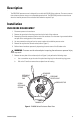
Description The PSKIT8100 pressure sensor is designed for use with the EH8100 Series enclosure. The sensor ensures that enclosure pressure stays at an acceptable operation level. The PSKIT8100 provides contact closure when the internal pressure of the enclosure falls below the required 5 psi. Installation ENCLOSURE DISASSEMBLY 1. Disconnect power to the enclosure. 2. Remove the ground wire from the ground stud on the back of the enclosure. 3. Remove the electrical connector from the rear of the enclosure.
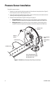
Pressure Sensor Installation To install the pressure sensor: 1. Remove the screw located inside the top portion of the enclosure’s rear plate (refer to Figure 2). Insert the pressure sensor tube fitting into the hole. 2. Loosen the camera sled mounting screws (refer to Figure 2). Slide the sensor bracket under the mounting screws and ground lug. Tighten the screws. 3. Connect the wire leads (refer to Figure 2 and Figure 3 on page 7): a.
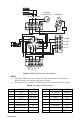
HEATER PRESSURE SENSOR SWITCH HEATER AC NEUT THERMOSTAT AC LINE FUSE PP ZOOM PP FOCUS PP COM IRIS FOCUS ZOOM LENS COM PP +5V Figure 3. EH8100 Series Enclosure: Wiring Diagram NOTES: • Consult the C1420M manual section dealing with model number listings for the wattage and number of heaters for the particular model that you are using. • Terminal block only on the EH8106. The EH8104 does not have a terminal block for lens presets. Table A. Pin Numbers and Descriptions PIN NO.
Enclosure Reassembly and Recharging REASSEMBLY When the enclosure is disassembled, it should be recharged after reassembly and prior to installation. Recharging requires the use of a Pelco EH8000RKIT recharge kit (or equivalent) and applicable O-ring kit, part EH8004ORKIT or EH8006ORKIT. To prepare the enclosure for recharging: 1. Once the enclosure has been disassembled, remove the O-ring from the rear plate and install a new O-ring in the O-ring groove. 2.
REVISION HISTORY Manual # C1445M C1445M-A Date 12/95 5/96 C1445M-B C1445M-C C1445M-D 5/96 8/00 11/04 C1445M-E 2/09 Comments Original version. Updated to include corrections to reference callouts in Section 3.4. Updated Figure 3. All changes in response to ECO# 95-220 and 96-131. Revised to include updated Figures 2 and 4. Revised installation instructions and wiring diagram layout. Updated manual to new format. Factory preset for regulator changed to 12 psi per EC0#04-9807.
C1445M-E (2/09)
PRODUCT WARRANTY AND RETURN INFORMATION WARRANTY Pelco will repair or replace, without charge, any merchandise proved defective in material or workmanship for a period of one year after the date of shipment.
www.pelco.com Pelco, Inc.