INSTALLATION/OPERATION ® PelcoNet™ NET300 Multimedia Transmission Via Network C2908M-B (4/05)
Contents Important Safeguards and Warnings . . . . . . . . . . . . . . . . . . . . . . . . . . . . . . . . . . . . . . . . . . . . . . . . . . . . . . . . . . . . . . . . . . . . . . . . . . . . . . . . . . . . . .6 Regulatory Notices . . . . . . . . . . . . . . . . . . . . . . . . . . . . . . . . . . . . . . . . . . . . . . . . . . . . . . . . . . . . . . . . . . . . . . . . . . . . . . . . . . . . . . . . . . . . . . .6 What is the Pelconet NET300 Transmission System? . . . . . . . . . . . . . . . . . . .
Recording and Viewing the Display On A PC . . . . . . . . . . . . . . . . . . . . . . . . . . . . . . . . . . . . . . . . . . . . . . . . . . . . . . . . . . . . . . . . . . . . . . . . . .67 Choosing Where to Store the File . . . . . . . . . . . . . . . . . . . . . . . . . . . . . . . . . . . . . . . . . . . . . . . . . . . . . . . . . . . . . . . . . . . . . . . . . . . . . .67 Recording a Snapshot from Video . . . . . . . . . . . . . . . . . . . . . . . . . . . . . . . . . . . . . . . . . . . . . . . . .
List of Illustrations 1 2 3 4 5 6 7 8 9 10 11 12 13 14 15 16 17 18 19 20 21 22 23 24 25 26 27 28 29 30 31 32 33 34 35 36 37 38 39 40 41 42 43 44 45 46 47 48 49 50 51 52 53 54 55 56 4 Front Panel Connections . . . . . . . . . . . . . . . . . . . . . . . . . . . . . . . . . . . . . . . . . . . . . . . . . . . . . . . . . . . . . . . . . . . . . . . . . . . . . . . . . . . . . . . . . . .11 Rear Panel Components . . . . . . . . . . . . . . . . . . . . . . . . . . . . . . . . . . . . . . . . . . . . . . . . .
List of Tables A B C C2908M-B (4/05) Pin Assignments . . . . . . . . . . . . . . . . . . . . . . . . . . . . . . . . . . . . . . . . . . . . . . . . . . . . . . . . . . . . . . . . . . . . . . . . . . . . . . . . . . . . . . . . . . . . . . . . .24 Terminal Command Reference . . . . . . . . . . . . . . . . . . . . . . . . . . . . . . . . . . . . . . . . . . . . . . . . . . . . . . . . . . . . . . . . . . . . . . . . . . . . . . . . . . . . . .54 Live Video Page Indicators . . . . . . . . . . . . . . . . .
Important Safeguards and Warnings Observe the following warnings before installing and using this product. 1. Read these instructions. 2. Keep these instructions. 3. Heed all warnings. 4. Follow all instructions. 5. Do not use this apparatus near water. 6. Clean only with dry cloth. 7. Do not block any ventilation openings. Install in accordance with the manufacturer’s instructions. 8.
What is the Pelconet NET300 Transmission System? The PelcoNet™ NET300 transmission system is technology that lets you view video in real time across a LAN (local area network) and even WANs (wide area networks). This technology is based on the TCP/IP protocol suite and Ethernet technology, providing compatibility with today’s networking standards.
Instructions for the Network Administrator The PelcoNet NET300 transmission system allows live video transmission to be viewed over TCP/IP-based networks. This section is intended to help the network administrator know what is involved with installing this product and how it will affect the network. The person installing the product will need the following information about the network to make the network function properly.
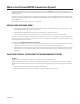
MINIMUM PC REQUIREMENTS (AS NEEDED) • PC (Pentium® 4 microprocessor, 1.6 GHz) with Windows 98/2000/XP operating system • Network card • Internet Explorer 6.0 (or higher) or free serial interface and terminal program • Screen resolution of 1024 x 768 or higher, 16- or 32-bit pixel color resolution NOTE: Old video cards that do not support YUV encoding require 16-bit color resolution.
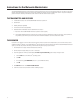
Overview NOTE: This manual refers to the PelcoNet NET300 transmission system unit when discussing features, functions, or specifications that apply to both transmitter and receiver models. “Receiver,” as used in this manual, refers to a PelcoNet NET300 transmission system receiver unless otherwise noted.
FRONT PANEL COMPONENTS The PelcoNet NET300 transmission system uses a compact design. For that reason connectors are placed on both the front and rear panels. Key: 1 = 2 3 4 5 6 = = = = = Terminals for alarm input and relay output • Two alarm input terminals (LN1/LN2) • Two relay terminals (R) (for one relay) • Two ground terminals (GND) • (The two unmarked terminals are not supported.
Typical Applications There are two ways to make a high performance multimedia transmission system for Ethernet networks: • One way is to use just the transmitter and connect it through the Ethernet network to a PC with a web browser at the receiving end. • Another way is to connect the transmitter through the Ethernet network to a receiver. This is often called a box-to-box connection because it uses two PelcoNet NET300 transmission system units.
HUB TRANSMITTER Video In RS232/422/485 CAMERA RECEIVER Video Out RS232/422/485 MONITOR Figure 4.
HUB TRANSMITTER Video In RS232/422/485 VIDEO DATA SPECTRA RECEIVER Video Out MONITOR RS232/422/485 KEYBOARD DATA Figure 5.
HUB TRANSMITTER Video In RS232/422/485 VIDEO GENEX SPECTRA DATA SPECTRA SPECTRA RECEIVER Video Out MONITOR RS232/422/485 KEYBOARD DATA Figure 6.
HUB TRANSMITTER Video In RS232/422/485 CAMERA BROWSER Figure 7. LAN Browser-To-Box Connection (Transmitter, Browser, Fixed Camera) HUB TRANSMITTER Video In RS232/422/485 VIDEO DATA SPECTRA BROWSER Figure 8.
HUB TRANSMITTER Video In RS232/422/485 VIDEO GENEX SPECTRA DATA SPECTRA SPECTRA BROWSER Figure 9.
CLOVIS SERVER 1 OR MORE PCs 1 OR MORE PCs ROUTER NEW YORK SERVER • • • • • • • • • • • • • • • ROUTER HUB HUB TRANSMITTER Video In RS232/422/485 CAMERA RECEIVER Video Out RS232/422/485 MONITOR Figure 10.
CLOVIS SERVER 1 OR MORE PCs 1 OR MORE PCs NEW YORK SERVER • • • • • • • • • • • • • • • ROUTER ROUTER HUB HUB TRANSMITTER Video In RS232/422/485 VIDEO DATA SPECTRA RECEIVER Video In RS232/422/485 DATA MONITOR KEYBOARD Figure 11.
CLOVIS SERVER 1 OR MORE PCs 1 OR MORE PCs NEW YORK SERVER • • • • • • • • • • • • • • • ROUTER ROUTER HUB HUB TRANSMITTER Video In RS232/422/485 VIDEO GENEX SPECTRA DATA SPECTRA SPECTRA RECEIVER Video Out MONITOR RS232/422/485 KEYBOARD DATA Figure 12.
CLOVIS SERVER 1 OR MORE PCs ROUTER 1 OR MORE PCs • • • • • • • • • • • • • • • HUB NEW YORK SERVER ROUTER HUB TRANSMITTER Video In RS232/422/485 CAMERA BROWSER Figure 13. WAN Browser-To-Box Connection (Transmitter, Browser, Fixed Camera) CLOVIS SERVER 1 OR MORE PCs 1 OR MORE PCs ROUTER • • • • • • • • • • • • • • • HUB NEW YORK SERVER ROUTER HUB TRANSMITTER Video In RS232/422/485 VIDEO DATA SPECTRA BROWSER Figure 14.
CLOVIS SERVER 1 OR MORE PCs 1 OR MORE PCs ROUTER • • • • • • • • • • • • • • • HUB NEW YORK SERVER ROUTER HUB TRANSMITTER Video In RS232/422/485 VIDEO GENEX SPECTRA DATA SPECTRA SPECTRA BROWSER Figure 15.
NET350 TRANSMITTER ETHERNET CONNECTION TO NETWORK (LAN/WAN) Video In RS232/422/485 PELCO KEYBOARD 12 VAC VIDEO DATA GENEX RXRX+ 4 3 2 1 5 6 7 8 KBD200A/ KBD300A STRAIGHT CABLE TXTX+ RXRX+ GND 12 V SPECTRA 12VDC PV140 PC WORKSTATION Figure 16.
Hardware Installation Refer to Appendix A — Connecting PelcoNet NET300 to Different Components for examples of how to connect equipment. CONNECTING VIDEO SOURCES OR DISPLAYS • The NET300 transmitter’s BNC Video In socket accepts color or black-white sources and automatically detects whether it is PAL or NTSC. The video input has an internal termination of 75 ohms. • The NET300 receiver’s BNC Video Out socket can be connected to any PAL or NTSC video monitor or VCR with a composite PAL or NTSC input.
WARNING: The maximum rating of the alarm contact is 30 VDC and 8 mA. On the plug-in terminal block, attach conductors to the alarm input (IN1 and IN2) and ground conductor (GND) terminals. (Insert a small screwdriver tip in the square hole and push hard enough to open the corresponding round hole. Insert the wire in the round hole.) R (RELAY) IN1 (ALARM INPUT1) NOT USED + (POWER) NOT USED 30 V GND GND IN2 (ALARM INPUT2) (POWER) R (RELAY) Figure 17.
CONNECTING TO A LAN Refer to Figure 18. You can connect the NET300 to a 10/100BASE-T network either directly or through a hub. To do so, plug a standard Cat5 UTP cable with RJ-45 connectors into the NET300’s Ethernet socket. IN1 R + Ethernet GND IN2 R Figure 18. Connecting to the LAN Port CONNECTING POWER The NET300 has no power switch. The power supply comes with the attached orange terminal block plug. To apply power do the following: 1.
Configuration BOX-TO-BOX CONNECTION The following explains a box-to-box connection. 1. First, transmitter and receiver need to be configured appropriately. If the units are supposed to be operated in different subnets, a gateway IP address must be configured. Use the Live video receiver IP address field to address the destination. Enter the settings using either a terminal program or a web browser. 2.
GETTING STARTED NOTE: NET-Manager is a program that can make it easier to manage PelcoNet units in local networks. The program and manual (C2901M) are on the resource CD that comes with your PelcoNet unit. Refer to the manual for instructions. The only NET-Manager features available to the NET300 include scanning to see your units’ IP and MAC addresses, changing IP addresses, and viewing the setup pages with the browser. 1. Start your web browser. 2.
GENERAL MATRIX CONTROL WITH LIVE VIDEO 1 MATRIX CONTROL WITH LIVE VIDEO 2 MATRIX CONTROL WITH MJPEG SERVER PUSH GENEX MUX WITH LIVE VIDEO 1 GENEX MUX WITH LIVE VIDEO 2 GENEX MUX WITH MJPEG SERVER PUSH SPECTRA DOME SYSTEM WITH LIVE VIDEO 1 SPECTRA DOME SYSTEM WITH LIVE VIDEO 2 SPECTRA DOME SYSTEM WITH MJPEG SERVER PUSH VIDEO 1 ESPRIT SYSTEM WITH LIVE VIDEO 1 VIDEO 2 ESPRIT SYSTEM WITH LIVE VIDEO 2 SERVER PUSH ESPRIT SYSTEM WITH MJPEG SERVER PUSH HOME CONTROL KEYBOARD CONTROL WITH LIVE VIDEO 1 SETUP
GENERAL UNIT NAME UNIT ID PASSWORD LEVEL PASSWORD PASSWORD CONFIRM DATE FORMAT UNIT DATE UNIT TIME TIME ZONE TIME SERVER IP ADDRESS HARDWARE VERSION SOFTWARE VERSION SOFTWARE UPLOAD UPLOAD PROGRESS CONFIGURATION DOWNLOAD CONFIGURATION UPLOAD VIDEO DECODER VIDEO MONITER NAME VIDEO OUTPUT STANDARD ALARM HOME SETUP ALARM INPUT 1/2 CONNECT ON ALARM NUMBER OF ADDRESS LIVE VIDEO TRANSMITTER IP ADDRESS REMOTE TRANSMITTER PASSWORD LIVE VIDEO AUTO-CONNECT RELAY IDLE STATE OPERATING MODE RELAY FOLLOWS RELAY NAM
SETUP PAGES Figure 22.
Figure 23. PelcoNet NET300 Receiver Setup Page NOTE: The Set button within a box on a configuration page applies to all the fields within that box. You can change all the fields in a box and then click Set once and all the changes within that box will be saved. All configuration items are stored in nonvolatile memory so they are kept when the unit is powered down. Some configurations apply only to transmitters (for example, camera settings) while others apply to both transmitters and receivers.
CONFIGURATION PAGE FOR GENERAL SETTINGS The unit identification, password, date and time, time server, version information, and software update settings make up the General Settings configuration page. All units have a real-time clock set during manufacture. However, time and date can be changed anytime; for example, when the units are operated in different time zones. Version numbers for the hardware and firmware are for information only. Whenever you need technical support, have these numbers ready.
Configuration Item Default Setting Unit name None (For future development.) The Unit name identifies the device; for example, in the event of an alarm, this name would be displayed in the video image, depending on the configuration. You can enter up to 31 alphanumeric characters. Unit ID None (For future development.) The Unit ID identifies the device. You can enter up to 31 alphanumeric characters. Password level None Select the password level from the pull-down menu.
Configuration Item Default Setting Time server IP address 0.0.0.0 Description Enter the IP address of a TIME protocol server and then click Set. The time and date are automatically synchronized every two hours to this Internet server. This feature does not adjust for Daylight Saving Time; you should adjust manually as needed. Hardware version N/A Read-only hardware version number. This contains unique serial number, type of hardware, and revision.
CONFIGURATION PAGE FOR MPEG-4 VIDEO SETTINGS (TRANSMITTER ONLY) MPEG-4 encoder and live page settings make up the configuration page for MPEG-4 video settings. The table that follows describes configuration items. Figure 25. Configuration Page for MPEG-4 Video Settings (Only One Example Shown) NOTE: In a box-to-box connection, the receiver monitor displays only Encoder 1 settings; Encoder 2 settings are not displayed.
Configuration Item Default Setting Description Camera Camera 1 Enter a camera name. Camera name stamping Off Use the pull-down menu to select a screen option (Top or Bottom) where the camera name will be displayed. Or select Off. Time stamping Off Use the pull-down menu to select a screen position (Top or Bottom) where the current time will be displayed. Or select Off.
Configuration Item Default Setting Description Frame skip ratio 1 Enter a skip value for images. • • Video resolution CIF Use the pull-down menu to choose the video resolution (QCIF, CIF, 2CIF, 4CIF, or custom) for viewing and recording. See the Preset Parameter Name field for descriptions of options. Field mode Interlaced This setting lets you select the field mode for video transmission.
CONFIGURATION PAGE FOR VIDEO DECODER SETTINGS (RECEIVER ONLY) Video monitor name and video output standard make up the configuration page for video decoder settings. The table that follows describes configuration items. Figure 26. Configuration Page for Video Decoder Settings Configuration Item Default Setting Description Video monitor name N/A Enter a name (31 characters maximum) for the monitor.
CONFIGURATION PAGE FOR ALARM SETTINGS The PelcoNet NET300 transmission system is not only a multimedia gateway but also a security device and, therefore, has many features related to security applications. The configuration page for alarm settings lets you configure your unit for surveillance applications. In most surveillancerelated applications, the receiver is located in a secure center-type environment while the transmitter is located at the site to be monitored. Figure 27.
Figure 28. Motion Detection Screen Figure 29.
The set of alarm features is explained below. Configuration Item Default Setting Description Video motion alarm N/A The system has a video motion detection feature. The video scene is monitored constantly for relevant motion. NOTE: Use of the motion detection feature is recommended only indoors and under controlled lighting conditions; it is not recommended in dim lighting. The following conditions must be met for motion detection to function: • Motion detection must be activated.
Configuration Item Default Setting Video loss alarm Off Alarm input 1 Off/High Description If you select On, the signal from the video source (the camera in most cases) is monitored constantly for interruption. If no signal is received, the NET300 triggers an alarm. 1. Select On from the pull-down menu if you want to activate an alarm through an external alarm sensor. 2. Select High or Low for the voltage level to activate the alarm. 3.
CONFIGURATION PAGE FOR RELAY SETTINGS You can use the configuration page for relay settings to specify parameters such as normally open or normally closed switching and bistable and monostable operation of the output. Figure 30.
Configuration Item Default Setting Idle state Open Select Open (N.O. at zero current) if the relay will operate as a normally open contact or Closed (N.C. with current) if it will operate as a normally closed contact. Operating mode Bistable Select the relay’s operating mode. Description • • Relay follows Off When you select the default Bistable mode, the relay will stay in the idle or active state for an indefinite period.
CONFIGURATION PAGE FOR COM INTERFACE SETTINGS You can use this configuration page to set the parameters of the RS232/422/485 serial interface port. Figure 31.
Configuration Item Default Setting Serial port function Terminal Description Select a controllable device from the pull-down menu: Terminal, Transparent, or Pelco Prot (protocol). If the port must transmit data transparently, select Transparent. You can use Pelco Prot to send any kind of control data for a Spectra, Esprit, Genex, or a Pelco matrix. Baud rate 19200 Use the pull-down menu to select a transmission rate from 600 to 115200 baud. Refer to Appendix A for settings.
CONFIGURATION PAGE FOR LOCAL COM INTERFACE – KEYBOARD You can use this configuration page to set the parameters for a local Com port so you can connect a Pelco keyboard to your computer. This lets you control a device through the keyboard; for example, a camera can be controlled from the browser with the Pelco keyboard. You can also use this feature to transmit serial data from your computer to the PelcoNet unit, or vice versa. Figure 32.
4. On the PelcoNet NET300 Setup Page (Figure 22), select Interface Settings COM1. Use the pull-down menu to set the serial data port to Transparent. Also set the baud rate for the connected external device you want to control. 5. Finally, from the Device Controls page (Figure 36), select Keyboard. This takes you to the “Keyboard Control with live video” page (Figure 41). The COM port is open and you can send transparent data from your PC COM port to the PelcoNet COM port, and vice versa.
. Configuration Item Default Setting Unit IP address 10.0.0.1 Enter a unique IP address that is valid for your network. The preconfigured default IP address allows for (transmitter) or easy configuration in closed environments. You can use a cross-over cable to connect directly to a PC. 10.0.0.2 (receiver) NOTE: Changing the IP address also affects the current browser connection. You will have to reset the NET300 and enter the new URL to regain connectivity to the unit. Subnet mask 255.255.0.
CONFIGURATION USING A TERMINAL PROGRAM Using a terminal program (for example, the Windows application HyperTerminal) on a computer connected to the RS232/422/485 port on the NET300 provides limited configuration and control capabilities. Do the following: 1. In the terminal program on your PC, ensure that the PC’s COM port is set up properly (default properties are 19200 baud, 8 bits, no parity, 1 stop bit, and no flow control) and that the local terminal echo is disabled. 2.
TERMINAL PROGRAM TRANSMITTER MENU STRUCTURE The following describes the terminal program transmitter menu structure. The menu items and commands are enclosed in single quotation marks. Do not enter the quotation marks. Information and current settings are displayed to the right of the commands. Refer to the Command Reference section for descriptions of the commands.
r – RCP+ Menu ‘e’ Local video coder number ‘D’ Remote video decoder number ‘c’ Display connection list ‘1’ Connect to Alarm IP ‘2’ Disconnect this Connection ‘3’ Disconnect all Connections ‘5’ Join Stream ‘x’ Leave this Menu ‘?’ This Menu 1 1 0.0.0.0 0.0.0.0 m – Misc Menu ‘v’ ‘x’ ‘?’ Get Version Info Leave this Menu This Menu TERMINAL PROGRAM RECEIVER MENU STRUCTURE The following describes the terminal program receiver menu structure. The menu items and commands are enclosed in single quotation marks.
COMMAND REFERENCE The following table gives an overview of the available commands. Table B. Terminal Command Reference Cmd 54 Description ? This command redisplays (refreshes) the current menu. 1 Use this command to connect to the receiver in a box-to-box setup. 2 Use this command to sever this connection to the unit. 3 Use this command to sever all connections to the unit. 5 Use this command to join the stream of video from the NET300 transmitter.
Operation LIVE VIDEO AND SERVER PUSH VIDEO PAGES The Live Video pages show a real-time picture of a camera view with update rates and image quality similar to a box-to-box configuration. It can be configured for bandwidth use and for various image quality settings. (Live video is accessible only through a NET300 transmitter and not through a NET300 receiver.) The Server Push pages show still pictures that are updated periodically, and image quality is fixed.
Figure 34. Live Video and Server Push Pages (Transmitter Shown) 1. To access the PelcoNet NET300 transmission system home page, you must first connect to the Internet/intranet network and open Internet Explorer (the browser). 2. Then, enter the IP address in the address box. The home page appears. 3. Click either Video 1 or Video 2 or Server Push on the home page. To exit any page, click an option at the top of the page.
DISPLAYING VIDEO ON A WEB BROWSER The NET300 uses MPEG-4 for transmitting video across the network. This enables transmission to standard web browsers of either live video (Video 1 or 2 mode) or a stream of still images (Server Push mode). • To activate the live video feature, click either Video 1 or Video 2 above the video window on the PelcoNet NET300 transmission system home page (refer to Figure 35). The unit transmits using MPEG-4 format for display in the browser.
Figure 36. Device Controls Page (Transmitter Only) The live video control pages include representations of keys that let you control various functions (in addition to showing the camera display). Use the mouse pointer and click the left mouse button to enable options and operate controls on the screen. Click outside the options to disable a radio button or selection button. Live video pages let you choose the size of the video viewing area.
MATRIX LIVE VIDEO/SERVER PUSH PAGE CONTENTS Figure 37.
• AUX ON button to activate an auxiliary • AUX OFF button to deactivate an auxiliary • ACK button to close a message when programming a pattern on the CM6700 only • SET check box to use in programming presets and patterns The following are arrayed under “Lens”: • Iris open and close buttons • Focus far and near buttons • Zoom out and in buttons The following are arrayed under “Pan/Tilt”: • Eight direction arrow buttons • Home button in the center to return the camera to its home position (p
GENEX LIVE VIDEO/SERVER PUSH PAGE CONTENTS Figure 38.
The following are arrayed down the right side of the page: • Radio buttons for 16 cameras • Iris open and close buttons • Focus far and near buttons • Zoom out and in buttons • Eight direction arrow buttons with a home button in the center to return the camera to its home position (preset 1) • Ten numbered buttons to use with the Pres and Pattern buttons to activate a preset and run patterns • A SET check box to use in programming presets and patterns • A Pattern button to run a pattern for e
SPECTRA LIVE VIDEO/SERVER PUSH PAGE CONTENTS Figure 39.
The following are arrayed under “Presets”: • Ten numbered preset buttons • Pres (preset) button • Clear button • A SET check box The following are arrayed under “Pattern”: • A Start pattern button • A Stop pattern button “In Control” or “No Control” indicates whether you have control of the camera. Recording control buttons are beneath the picture (live video page only).
ESPRIT LIVE VIDEO/SERVER PUSH PAGE CONTENTS Figure 40.
The following are arrayed under “Presets”: • Ten numbered preset buttons • Pres (preset) button • Clear button • A SET check box The following are arrayed under “Pattern”: • A Start pattern button • A Stop pattern button • A Wiper button “In Control” or “No Control” indicates whether you have control of the camera. Recording controls buttons are beneath the picture (live video page only).
RECORDING AND VIEWING THE DISPLAY ON A PC Video 1 and 2 and live video control pages let you keep snapshots (still pictures) and record the camera video display on a PC’s hard drive and play it back later. The file is recorded on the hard drive of the PC on which you are viewing the picture. The controls are a row of buttons beneath the screen. NOTE: When video files are saved, an extra file (.ind extension) is created that lets you see the video in Pelco’s MPEG Viewer.
Figure 42. Viewer Screen 2. Click the Open button. A browse dialog box opens. Navigate to the recorded file (.mp4 extension) you want to view. Click the file to highlight it, and then click Open. 3. Click Play on the viewer to begin playback. The start and end locations are shown below the slide control. A counter marks your location in the file. 4. Use the Pause button to temporarily halt playback. You can change your location in the file by moving the pointer on the slide control.
Software Upload Units have flash EPROMs for software upgrades in the field. These upgrades can be done directly from the web browser. To do so: 1. Obtain the latest PelcoNet NET300 transmission system software from Pelco (http://pelco.com). 2. Use the browser to select the General Settings configuration page of your unit. 3. Use the Browse button in the Software upload field to select the correct new firmware file. 4. Click the Upload button. The Upload progress field shows how the upload is proceeding.
Resetting the NET300 To reset the unit, type a forward slash (/) and reset at the end of the unit’s address in the Internet Explorer browser address window, and then press Enter.
Troubleshooting If the following instructions fail to solve your problem, contact Pelco Technical Support at 1-800-289-9100 for help. You should have the serial number from the bottom of the unit and the firmware version ready in case they are needed. Do not try to repair a unit yourself. Opening it immediately voids any warranty. Leave maintenance and repairs to qualified technical personnel. Swap a defective unit with a replacement unit and return the defective one for repair.
TROUBLESHOOTING THE VIDEO CONNECTION If no video or a distorted video image is displayed at the receiver during a connection to a transmitter: 72 • Make sure to use the right unit for your application: a camera can only be connected to a transmitter, never to a receiver. • Make sure the video input on the transmitter is properly terminated. • Make sure the camera is switched on and the coaxial cable is connected to the transmitter.
Specifications NETWORK PROTOCOL & STANDARDS COMPATIBILITY Network Protocols: RTP, RTCP, UDP, TCP, IP, HTTP, SNMP, IGMP, ICMP, ARP Video Coding: MPEG-4 (M-JPEG in Server Push mode only) Video Frame Rate: Up to 30 images/second INTERFACE Video Input or Output: 1, BNC, PAL/NTSC, 75 ohms, 1 Vp-p LAN Interface: Ethernet 10/100BaseT autosensing, RJ-45 LAN Data Rate: 9.6 Kbps to 1.
Glossary 74 10BASE-T IEEE 802.3 specification for 10 Mbs Ethernet ARP Address Resolution Protocol Baud Rate Data transmission rate bps Bits per second, the actual data rate Cat5 Cable Type of cable used on a LAN to connect computers, printers, and transmitters and receivers to a hub on the network CIF Common Intermediate Format; video format with 352 x 288 pixels Default Gateway The router’s IP address (for example, 192.168.0.
Subnet Mask A mask that explains which part of an IP address is the network address and which part composes the hose address; it is usually expressed in dotted-decimal notation (for example, 255.255.255.192) TCP Transfer Control Protocol UDP User Datagram Protocol URL Uniform Resource Locator UTP Unshielded Twisted Pair WAN Wide Area Network. Multiple LANs connected together, usually over a great distance.
Appendix A — Connecting Pelconet To Various Components Some of the connection examples that follow require a DB9 cable. Refer to the following figure when one is needed. DB9 TX+ TX- RX+ RX- RX+ RX- TX+ TX- TO RECEIVER ESPRIT SPECTRA PIN 1 2 3 4 5 6 7 8 9 1 2 3 4 5 6 7 8 9 RS-422/RS-485 RX+ (RECEIVE DATA PLUS) TX- (TRANSMIT DATA MINUS) GND TX+ (TRANSMIT DATA PLUS) RX- (RECEIVE DATA MINUS) Figure 43.
CONNECTING PELCONET TO VARIOUS COMPONENTS WITH ASSORTED KEYBOARDS CONNECTION SCENARIO 1 – USING A KBD300A IN DIRECT MODE Refer to Figure 44 and the instructions that follow. TRANSMITTER Video In TXTX+ RS232/422/485 P PROTOCOL ONLY RX+ RX- RECEIVER OR SPECTRA 4800, 8, NONE, 1 RECEIVER Video Out RS232/422/485 KBD300A 12 VAC 4800, 8, NONE, 1 MONITOR RX(-) RX(+) 4 3 2 1 5 6 7 8 DIRECT MODE STRAIGHT CABLE Figure 44. KBD300A (Direct Mode) Connected to a Receiver or Spectra Dome System 1.
6. Connect the monitor. 7. Refer to Figure 43 and Figure 44. Splice the supplied DB9 cable into the Spectra/Esprit or receiver cable. Use P protocol only. 8. Plug the DB9 cable into the RS232/422485 port on the transmitter. (In the Interface Mode field, select RS-422-485.) The data format should be 4800, 8, no parity, 1. 9. Connect the camera’s video to the transmitter. CONNECTION SCENARIO 2 – USING A KBD4000 FOR MULTIPLEXER CONTROL Refer to Figure 45 and the instructions that follow.
2. On the receiver side, connect TX− on the DB9 cable to terminal 7 on the wall block. Connect TX+ on the DB9 cable to terminal 8 on the wall block. Connect RX− on the DB9 cable to terminal 2 on the wall block. Connect RX+ on the DB9 cable to terminal 1 on the wall block. 3. Connect a 12 VAC power supply to terminals 3 and 4 on the wall block. 4. Connect the wall block to the KBD4000 with an RJ-45 straight cable. (Note that DIP switches 4 and 8 on the KBD4000 must be set ON.) 5. Connect the monitor. 6.
CONNECTION SCENARIO 3 – USING A CM9760-KBD Refer to Figure 46 and the instructions that follow. TRANSMITTER Video In RS232/422/485 4 3 2 1 4800, 8, EVEN, 1 5 6 7 8 RX + RX TX + TX - CM9760-CC1 FLIPPED CABLE SERCOM PORT PROGRAMMED FOR KBD RECEIVER Video Out RS232/422/485 CM9760KBD POWER PAK KEYBOARD 4800, 8, EVEN, 1 4 3 2 1 RX RX + MONITOR CARD CAGE 5 6 7 8 TX + TX STRAIGHT CABLE Figure 46. CM9760KBD Connected to a CM9760-CC1 Controller 1.
7. Plug the DB9 cable into the RS232/422/485 port on the transmitter. (In the Interface Mode field, select RS-422/485.) The data format should be 4800, 8, even, 1. 8. Connect an RJ-45 flipped cable from the wall block to Sercom port 5 on the CC1’s rear panel. 9. Connect one of the three monitor outputs on the rear of the controller to the transmitter. CONNECTING A LOCAL KEYBOARD TO A PC Refer to Figure 47.
CONNECTING THE PELCONET’S COM PORT TO THE GENEX MULTIPLEXER’S COM OUT PORT Refer to Figure 48 and the instructions that follow. TRANSMITTER ETHERNET CONNECTION TO NETWORK Video In RS232/422/485 9600, 8, NONE, 1 PELCONET DB9 CONNECTOR PIN 2 RX GENEX COM OUT RJ-45 CONNECTOR PIN 6 TX PIN 3 TX PIN 4 RX PIN 5 GND PIN 5 GND GENEX COM MULTIPLEXER 8 1 IN 8 1 OUT Figure 48. Connecting PelcoNet to Genex Using the COM Port 1. Verify that the multiplexer has Version 4.
CONNECTING PELCONET TO A CM6700 AND KBD200A FOR REMOTE ASCII CONTROL Refer to Figure 49. This configuration lets an operator view and control cameras with a remote KBD200A keyboard. PELCONET REMOTE KBD200A ASCII MODE SETUP TRANSMITTER ETHERNET CONNECTION TO NETWORK (LAN/WAN) Video In RS232/422/485 PELCONET CM6700-MXB TRANSPARENT COM 2 (7-12) DATA PORT SW5 DIP SWITCH SETTINGS 2 RX......................7 TX 3 TX.......................12 RX 5 GND...................
CONNECTING PELCONET TO A CM6700 ASCII PORT Refer to Figure 50. This configuration lets an operator view and control cameras from a PC using a web browser. (The operator’s PC is not shown on the diagram.
CONNECTING PELCONET TO A CM9760-DT FOR REMOTE BROWSER CONTROL Refer to Figure 51. This configuration lets an operator view and control cameras from a PC using a web browser. (The operator’s PC is not shown on the diagram.
CONNECTING PELCONET TO CM9700 FOR REMOTE COMMUNICATION Refer to Figure 43 and Figure 52 and Figure 53. These configurations let an operator remotely view and control cameras connected to the CM9700.
LOCAL NODE: RECEIVING DATA AND VIDEO RECEIVER Video Out CAM INPUT TIE LINE CM9505-UPS ETHERNET CONNECTION TO NETWORK (LAN/WAN) RS232/422/485 TRANSPARENT DATA PORT USING INTERNET EXPLORER; SET TRANSPARENT DATA PORT SETTINGS: BAUD RATE 9600 8 DATA BITS EVEN PARITY 1 STOP BITS CM9760KBD 4 3 2 1 5 6 7 8 *WALL BLOCK CONNECTIONS * * TERMINAL SERCOM PORT PELCONET * * 1 2 7 8 TX+ TXRXRX+ RX+ RXTXTX+ CM9700-NW1 RJ-45 WALL BLOCK NOT SUPPLIED SERCOM PORT PROGRAMMED FOR NETWORK COMMUNICATION (STRAIGHT C
CONNECTING A PELCONET TRANSMITTER TO THE CM6800 ASCII PORT Refer to the transmitter portion of Figure 56. This configuration lets an operator view and control cameras from a PC using a web browser. (The operator’s PC is not shown on the diagram.) All settings are done in the CM6800 manager program or through a CM6800 menu. Note the following: • Port 2 defaults to ASCII and RS-232.
CONNECTING PELCONET TO A CM6800 AND KBD200A FOR REMOTE CONTROL Refer to Figure 56. This configuration lets an operator view and control cameras with a remote KBD200A keyboard. All settings are done in the CM6800 manager program or through a CM6800 menu. Note the following: • Port 2 defaults to ASCII and RS-232. • Ports 7 and 8 can be set to ASCII and RS-232 by using the CM6800 manager program (refer to Figure 54) or by using a CM6800 menu (refer to Figure 55). • Port 2 is recommended.
PELCONET CM6800 ASCII SETUP TRANSMITTER ETHERNET CONNECTION TO NETWORK (LAN/WAN) Video In SPECTRA COAXITRON PROTOCOL TRANSPARENT DATA PORT USING INTERNET EXPLORER; SET TRANSPARENT DATA PORT SETTINGS: BAUD RATE 9600 DATA BITS 8 PARITY ODD STOP BITS 1 RS232/422/485 2-RX 3-TX 5-GND 4 3 2 1 GND 5 6 7 8 RX - TX - STRAIGHT CABLE PELCONET TRANSPARENT CM6800-48X8 DATA PORT COM 2 2 RX.................................. 8 TX 3 TX................................... 1 RX 5 GND............................
Appendix B — Frequently Asked Questions (FAQs) 1. What Pelco devices can I control from my computer with PelcoNet? PelcoNet can control the following from Internet Explorer: • • • • • Spectra and Esprit Genex multiplexer CM9700 matrix (older CM9760s require CM9760 data translator) CM6700 matrix (through integrated ASCII port) CM6800 matrix 2. Can I view PelcoNet over the Internet? Yes. You will need a static IP address and enough bandwidth to view live video.
PelcoNet uses the MPEG-4 industry standard for video teleconferencing over the Internet. It provides the most effective use of bandwidth with excellent video quality. 13. I do not get live video in the browser but server push is working. What could be wrong? Verify that the ActiveX plug-in is installed and that your video is set to 16-bit color. Also check with your network administrator to verify that the TCP/IP ports PelcoNet uses are not being filtered and that you have enough bandwidth. 14.
Index A Installation (hardware) 24 Interface mode 47 Intra frame distance 37 IP address 7 Alarm indicator 42 Alarm input 1 43 Alarm input 2 43 Application diagrams 12 Auxiliaries (matrix) 60 Average n 42 K Keyboard control page L B Baud rate 66 47, 48 C Camera 37 Camera (matrix) 60 Camera name stamping 37 COM port 48 Configuration download 35 Configuration pages Alarm settings 40 Com interface settings 46 General settings 33 Local Com interface — keyboard 48 MPEG-4 video settings (transmitter only)
S Select area button 42 Serial interface 10 Serial port function 47 Server push 57 Server push page 55 Snapshots (record from video) 67 Snapshots (viewing) 67 Software upload 35, 69 Software version 10, 35 Spectra/Esprit protocol ID 47 Stop bits 47, 48 Storing files 67 Subnet mask 50 T Terminal program receiver menu structure 53 Terminal program transmitter menu structure 52 Time server IP address 35 Time stamping 37 Time zone 34 Tracker 42 Trigger relay 45 U Unified picture detection Unit date 34 Unit ID
PRODUCT WARRANTY AND RETURN INFORMATION WARRANTY Pelco will repair or replace, without charge, any merchandise proved defective in material or workmanship for a period of one year after the date of shipment. Exceptions to this warranty are as noted below: • Five years on FT/FR8000 Series fiber optic products and the following fixed camera models: CC3701H-2, CC3701H-2X, CC3751H-2, CC3651H-2X, MC3651H-2, and CC3651H-2X.
® Worldwide Headquarters 3500 Pelco Way Clovis, California 93612 USA USA & Canada Tel: 800/289-9100 Fax: 800/289-9150 International Tel: 1-559/292-1981 Fax: 1-559/348-1120 www.pelco.