
Manual


Overview
10
|
Overview
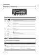
FRONT PANEL DESCRIPTION
No. Name Description
a
1
1
A NO COM Tx+ Rx+
NC Tx- Rx-
Power input socket. For connection of 12V adapter.
b
1
1
A NO COM Tx+ Rx+
NC Tx- Rx-
Press this switch to reset device to the factory default.
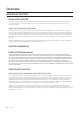
If you perform the factory reset, all your settings to device will be lost. For more information, please see Factory
Default (Page 13).
c
A Alarm input sensor terminal
1
1
A NO COM Tx+ Rx+
NC Tx- Rx-
Ground terminal.
NO/NC Relay control
COM Relay common
TX+/TX- RS-422/RS-485 Data line
RX+/RX-
RS-422 RX Data line
J
Disabled in RS-485 mode.
d
1
1
A NO COM Tx+ Rx+
NC Tx- Rx-
Video Encoder. Audio input terminal for sound input.
A microphone or other source of sound may be connected to this.
e
1
1
A NO COM Tx+ Rx+
NC Tx- Rx-
Video input BNC terminal.
f
1
1
A NO COM Tx+ Rx+
NC Tx- Rx-
Video output BNC terminal.
PTZ, Relay and Alarm Pin Assignments
Label Lead Label Lead
A Alarm TX+ RS-422 Data TX+
1
1
A NO COM Tx+ Rx+
NC Tx- Rx-
Ground TX- RS-422 Data TX-
NO Relay Normally Open RX+ RS-422 Data RX+
COM Relay Common RX- RS-422 Data RX-
NC Relay Normally Closed
a b d e fc