I N S T A L L A T I O N Endura NET5308T-EXP Eight-Input Dual-Stream Video Encoder ® For Use with NET5300B Multichannel Video Encoder Base Module C2655M-A (10/08)
Contents Regulatory Notices . . . . . . . . . . . . . . . . . . . . . . . . . . . . . . . . . . . . . . . . . . . . . . . . . . . . . . . . . . . . . . . . . . . . . . . . . . . . . . . . . . . . . . . . . . . . . . . . . . . . 5 Video Quality Caution . . . . . . . . . . . . . . . . . . . . . . . . . . . . . . . . . . . . . . . . . . . . . . . . . . . . . . . . . . . . . . . . . . . . . . . . . . . . . . . . . . . . . . . . . . . . . . . . . . 5 Frame Rate Notice Regarding User-Selected Options . . . . . .
List of Illustrations 1 2 3 4 5 6 7 8 9 10 11 12 13 14 15 16 17 18 19 20 21 22 23 24 25 Major Package Components. . . . . . . . . . . . . . . . . . . . . . . . . . . . . . . . . . . . . . . . . . . . . . . . . . . . . . . . . . . . . . . . . . . . . . . . . . . . . . . . . . . . . . . . . 8 Accessory Pack . . . . . . . . . . . . . . . . . . . . . . . . . . . . . . . . . . . . . . . . . . . . . . . . . . . . . . . . . . . . . . . . . . . . . . . . . . . . . . . . . . . . . . . . . . . . . . . . . . .
Regulatory Notices This device complies with Part 15 of the FCC Rules. Operation is subject to the following two conditions: (1) this device may not cause harmful interference, and (2) this device must accept any interference received, including interference that may cause undesired operation. RADIO AND TELEVISION INTERFERENCE This equipment has been tested and found to comply with the limits of a Class A digital device, pursuant to Part 15 of the FCC Rules.
Description The NET5308T-EXP multichannel dual stream video encoder is an enterprise-class, 8-input video encoding unit that is used exclusively with the NET5300B base module. Designed to accommodate the stringent requirements of high-performance video monitoring applications, each NET5308T-EXP converts eight channels of live analog video into dual MPEG-4 video streams at up to 4CIF resolution and 30 images per second (ips) per stream. The NET5308T-EXP captures up to eight audio inputs simultaneously.
Before You Begin Endura is a network system that requires a continuous amount of bandwidth to transmit true, live video. Therefore, always include your network administrator when planning and installing Endura components.
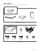
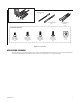
PACKAGE CONTENTS The following diagrams show the box contents. When installing the NET5308T-EXP, refer to these diagrams. SHIPPING BOX SAFETY INSTRUCTIONS INSTALLATION MANUAL NET5308T-EXP ACCESSORY PACK Figure 1. Major Package Components ACCESSORY PACK FRONT BEZEL KEY 2 EA. USA STANDARD T POWER CORD (110 VAC) 1 EA. UK STANDARD POWER CORD (250 VAC) 1 EA. EUROPEAN STANDARD POWER CORD (220 VAC) 1 EA. RACK MOUNT KIT RELAY TERMINAL BLOCKS 2 EA. ALARM TERMINAL BLOCKS 2 EA. Figure 2.
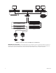
REAR MOUNT RAIL 2 EA. RACK MOUNT KIT FRONT MOUNT RAIL 2 EA. CHASSIS MOUNTING BRACKETS 1 EA. SHOWN ACTUAL SIZE PHILLIPS FLAT HEAD SCREW, 6-32 X 0.25-INCH 6 EA. PHILLIPS TRUSS HEAD SCREW, 8-32 X 0.375-INCH 6 EA. PHILLIPS FLAT HEAD SCREW, 10-32 X 0.5-INCH 4 EA. PHILLIPS PAN HEAD SCREW, 10-32 X 0.5-INCH 4 EA. CAGE NUT, 10-32 10 EA. Figure 3. Rack Mount Kit APPLICATION SCENARIO This section illustrates one possible application scenario featuring the NET5308T multichannel video encoder.
WS5000 SM5000 VCD5000 GIGABIT SWITCH KBD5000 USB NET5300B NVR5100 NET5308T-EXP #1 NET5308T-EXP #2 UP TO 8 SEB5100 UP TO 8 Figure 4. Security Network with One NET5300B and Two NET5308T-EXPs IMPORTANT NOTE. PLEASE READ. The network implementations in this document are shown as general representations only and are not intended to show detailed network topologies. Your actual network will differ, requiring changes or perhaps additional network equipment to accommodate the systems as illustrated.
Product Serial Number Placement Product serial number labels help identify your system and its factory configuration in the event that your NET5308T-EXP or its components require service. Two labels citing your product’s serial number are attached to your NET5308T-EXP. One large label is attached to the rear panel. A smaller label is attached to the front panel of the unit, behind the bezel.
Rack Mounting The NET5308T-EXP mounts into an industry-standard 19-inch (48 cm) equipment rack. The NET5308T-EXP occupies one rack unit (1.75 inches or 4.5 cm) of vertical rack space. The hardware necessary to mount the NET5308T-EXP into a rack is supplied with the unit. NOTES: • If you installed the NET5300B on a desktop, you can also place up to two NET5308T-EXP units on top of the NET5300B. (NET5308T-EXP units do not include rubber feet.
(3) SCREWS, 8-32 X 0.375 PHILLIPS TRUSS HEAD Figure 7. Assembling a Support Rail 3. Repeat step 2 for the other rail set. 4. If you are installing the unit into a square-hole rack: Insert 10 cage nuts into the square-hole rack as shown in Figure 8. Align the top and bottom cage nuts on the front racks with the top and bottom cage nuts on the rear racks. CAGE NUT CAGE NUT FRONT-MOUNT RAIL REAR-MOUNT RAIL Figure 8. Inserting Cage Nuts 5.
RACK FRONT RACK REAR (2) SCREWS, 10-32 X 0.5-INCH PHILLIPS PAN HEAD (2) SCREWS, 10-32 X 0.5-INCH PHILLIPS FLAT HEAD FRONT-MOUNT RAIL REAR-MOUNT RAIL Figure 9. Attaching Support Rails 6. Repeat step 5 for the second support rail assembly. 7. Tighten the 8-32 x 0.375-inch Phillips truss head screws that were attached to the front- and rear-mount rails in steps 2 and 3. 8. Place the unit onto the mount rails by sliding the chassis brackets onto the rails.
9. After the unit is in place, tighten the two thumbscrews to secure the unit to the rack. THUMBSCREW Figure 11.
Connections Familiarize yourself with the NET5308T-EXP rear panel before connecting any equipment to the unit. 1 2 3 4 A1 A2 A3 A4 5 6 7 8 A5 A6 A7 A8 SN AMPS Sample Text Audio/Video Apparatus 91KK FREQ 50/60HZ MO DE L SEC NO NO VOLTS Sample Text Mod el MFG BY PELCO, CLOVIS, CA 03267-39-0020 C C NC NC NO NO REV Sample Text MADE IN USA C C NC NC 100-200 VAC - 50/60 HZ 0.7 AMP Figure 12.
5. Apply a matching colored sticker (red or yellow) next to the USB connector on the NET5300B rear panel. This identifies the USB cable (red or yellow) that should be connected to this NET5308T-EXP. APPLY YELLOW LABEL USB “B” CONNECTOR A5 A6 A7 A8 SEC NO N NC NO N NC APPLY RED LABEL APPLY YELLOW LABEL NET5300B YELLOW USB CABLE USB “A” CONNECTOR NET5308T-EXP #2 USB “B” CONNECTOR RED USB CABLE A5 A6 A7 A8 SEC NO N NC NO N NC APPLY RED LABEL NET5308T-EXP #1 Figure 13.
Table B. Video Coaxial Cable Requirements Cable Type* Maximum Distance RG59/U 750 ft (229 m) RG6/U 1,000 ft (305 m) RG11/U 1,500 ft (457 m) *Cable requirements: 75-ohm impedance All-copper center conductor; steel-center conductor cable may result in poor performance All-copper braided shield with 95% braid coverage CONNECTING VIDEO INPUT The NET5308T-EXP automatically detects the video standard (PAL or NTSC) when you connect a video input. It accepts both color and black-white analog video.
CONNECTING LOOPING VIDEO The NET5308T-EXP supports looping video. It passes the video input to a monitor or other analog video device. To use looping video: 1. Connect a coaxial cable to the video out connector on the rear panel. NOTE: You may have to use a BNC installation tool to connect coaxial cables to the rear panel. 2. Connect the other end of the coaxial cable to the analog device. 3. After installation, use the Endura workstation to disable video termination for the video channel. 4.
CONNECTING RELAY DEVICES The NET5308T-EXP supports up to four relay devices. Use them to trigger external devices. The unit supports both momentary and continuous relay operation, either normally open or normally closed. You can operate the relay interactively, during an active connection, or automatically to coincide with certain events. Typical applications include activating a door, gate, or lock, or switching on lights or other electrical devices.
EXTERNAL FUSE NO POWER MAX: 30 VDC, 2 A 125 VAC, 0.5 A C A5 A6 A7 LOAD: LIGHT/SIREN A8 NO C NC NO C NC 100-200 VAC - 50/60 HZ 0.7 AMP Figure 17. Connecting a Relay Device CONNECTING ALARMS The NET5308T-EXP offers eight alarm inputs for external signaling devices, such as door contacts or motion detectors. Each alarm input can be either normally open or normally closed, either supervised or unsupervised.
Figure 19 illustrates the wiring configuration for supervised alarm inputs. NORMALLY CLOSED NORMALLY OPEN 10 K Ω 10 K Ω Figure 19. Supervised Alarm Input Wiring UNSUPERVISED ALARMS When an alarm is configured as an unsupervised alarm, the NET5308T-EXP triggers an alarm only when the normal alarm state (open or closed) changes. Figure 20 illustrates the alarm and no alarm conditions of an unsupervised alarm input. A normally closed alarm input can be defeated with a bypass.
Figure 22. Alarm Terminal Block Table D identifies the pin assignments for the terminal block. On the terminal block, pin 1 is on the left (refer to Figure 22). Table D. Alarm Pin Assignments Pin Label Lead 1 A1 Alarm 1 2 3 Ground A2 Alarm 2 A3 Alarm 3 4 5 Ground 6 7 8 Ground A4 Alarm 4 Ground These pins, labels, and leads also correspond to alarms 5–8 on the other alarm terminal block.
A5 A5 A6 A7 A8 NO C NC NO C NC 100-200 VAC - 50/60 HZ 0.7 AMP Figure 23. Connecting Alarms CONNECTING POWER The power supply incorporated into the NET5308T-EXP is tested and certified for high reliability applications. The unit has an autoranging power supply that adapts automatically to voltages between 100 VAC and 240 VAC (50/60 Hz). For greater reliability, you can also install an uninterruptible power supply (UPS) (not supplied).
Operation Refer to the WS5000 operation manual (C2624M) for details on how to access and configure the video inputs on the NET5308T-EXP. Configure the NET5300B before you configure any video inputs on the NET5308T-EXP. NOTE: To make sure that all diagnostic messages will appear to a system operator, leave at least one Endura workstation or VCD5000 video console display running at all times. FRONT PANEL CONTROLS AND INDICATORS Figure 24.
UNIT STARTUP To start the unit: 1. Unlock and open the bezel cover. Be careful not to drop the bezel cover; it is not attached directly to the unit. 2. Press the power button until it clicks. The power indicator glows. 3. Close and lock the bezel cover. POWER BUTTON Figure 25. Opening the Front Bezel Cover UNIT SHUTDOWN To shut down the unit: 1. Unlock and open the bezel cover. Be careful not to drop the bezel cover; it is not attached directly to the unit. 2. Press and release the power button. 3.
Troubleshooting If the following instructions fail to solve your problem, contact Pelco Product Support at 1-800-289-9100 or +1-559-292-1981 for assistance. Access the properties dialog boxes for the camera on the Endura workstation (refer to the WS5000 operation manual [C2624M]). Then note the following before calling Pelco: • Unit serial number: on the product label • Software version: located in the Advanced Properties window WARNING: Do not try to repair the unit yourself.
Specifications MODEL NUMBER NET5308T-EXP Multichannel dual stream video encoder that encodes video and audio and that controls data for transmission over a USB 2.0 link to a NET5300B base module VIDEO/AUDIO Video Standards NTSC/PAL/EIA/CCIR composite Video Coding MPEG-4 Video Streams 16, simultaneous, 2 per input Video Resolutions 4CIF 2CIF CIF QCIF NTSC 704 x 480 704 x 240 352 x 240 176 x 120 Video Inputs 8, BNC, looping, 75 ohms, 0.
POWER Power Input 100–240 VAC, 50/60 Hz, 0.7A, autoranging Cable Type 1 USA (117 VAC), 1 European (220 VAC), 1 UK (250 VAC) All, 3 prongs, molded connector, 6 ft (1.
PRODUCT WARRANTY AND RETURN INFORMATION WARRANTY Pelco will repair or replace, without charge, any merchandise proved defective in material or workmanship for a period of one year after the date of shipment. Exceptions to this warranty are as noted below: • Five years on fiber optic products and TW3000 Series unshielded twisted pair (UTP) transmission products. • Three years on Spectra® IV products. • Three years on Genex® Series products (multiplexers, server, and keyboard).
Pelco, Inc. Worldwide Headquarters 3500 Pelco Way, Clovis, California 93612 USA USA & Canada Tel: (800) 289-9100 Fax: (800) 289-9150 International Tel: +1 (559) 292-1981 Fax: +1 (559) 348-1120 www.pelco.