PELCO GENEX MX4000 Genex™ Series Simplex Multiplexer Installation/ Operation Manual LISTED UL ® C1927M (5/99) R Pelco • 300 W. Pontiac Way, Clovis • CA 93612-5699 USA • Pelco Online @ http://www.pelco.
CONTENTS Section Page IMPORTANT SAFEGUARDS AND WARNINGS ................................................................ 5 DESCRIPTION ................................................................................................................... 5 WHAT IS A VIDEO MULTIPLEXER? .......................................................................... 5 GENEX™ SERIES SIMPLEX MULTIPLEXERS ........................................................ 6 APPLICATIONS ............................................
LIST OF ILLUSTRATIONS Figure 1 2 3 4 5 6 7 8 9 10 11 12 13 14 15 16 17 18 Page Stand-Alone Multiplexer ..................................................................................... 7 Multiplexers with KBD4000 Keyboard ................................................................ 7 Multiplexers with KBD4000 Keyboards and MX4000SVR Server ..................... 8 Rack Installation .................................................................................................
(This page intentionally left blank.
IMPORTANT SAFEGUARDS AND WARNINGS Prior to installation and use of this product, the following WARNINGS should be observed. 1. Installation and servicing should only be done by qualified service personnel and conform to all local codes. 2. Unless the unit is specifically marked as a NEMA Type 3, 3R, 3S, 4, 4X, 6, or 6P enclosure, it is designed for indoor use only and it must not be installed where exposed to rain and moisture. 3. Only use replacement parts recommended by Pelco. 4.
Not only does the number of cameras affect the time gap, but so does the recording speed. The slower the recording speed, the longer the gap. Normal recording speed for full motion is the two-hour mode. But if you slow the recording speed down to record 12 hours, 48 hours, or 960 hours of video on a two-hour tape, it means that a lot of video is left out. Thus, the more cameras there are and the slower the recording speed, the longer the time gap becomes between recorded pictures for any one camera.
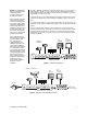
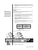
By adding a KBD4000 keyboard to the multiplexer (refer to Figure 2), you can control 1-16 multiplexers from up to 25 feet (7.6 m) away with the cable supplied with the keyboard. Greater distances between the multiplexer and keyboard can be obtained if you provide a Pelco KBDKIT(-X) and your own cable. NOTE: The KBD4000 keyboard in combination with a multiplexer provides Coaxitron® control of pan, tilt, and lens functions. A keyboard also gives you the added capability of controlling moveable cameras.
KBDKIT(-X) F2 F3 7 8 CAM PRESE T 0 MACR O F2 F3 7 8 CAM PRESE T 0 KBD4000 KEYBOARD (4 MAXIMUM) MACR O MONITOR (4 MAXIMUM) F2 F3 7 8 CAM PRESE T 0 MACR O F2 F3 7 8 CAM PRESE T 0 MACR O LOCAL PORT REMOTE PORT MX4000SVR Multiplexer Server GENEX™ Multiplexer Server Made In USA MAIN MONITOR OUTPUT FROM MULTIPLEXER MX4000SVR MULTIPLEXER SERVER SPOT MONITOR OUTPUT FROM MULTIPLEXER (OPTIONAL) DISPLAY RECORD DISPLAY RECORD TO OTHER MULTIPLEXERS DISPLAY RECORD MX4000 MULTIPLEXER
INSTALLATION Unpack and inspect all parts carefully. The following parts are supplied: 1 1 MX4000 Series multiplexer Rack ear kit 2 Rack ears 4 4-40 x .375-inch pan head screws 4 10-32 x .750-inch pan head screws Power cord 6-foot (1.8 m) data cable with RJ-45 connectors 1 1 Installation of the multiplexer varies according to the type of installation. The Basic Installation section covers the basic installation procedures for all applications.
3. Attach the rack ears (C) to the multiplexer. The rack ears are universal and can be used on either side of the unit. Attach the ears with the 4-40 x .375-inch screws (D) that are supplied with the ears. Only the two bottom holes on the rack ears are needed for mounting. 4. Install the multiplexer in the rack using the four 10-32 x .750-inch screws that are supplied. Proceed to the Cameras section. CAMERAS NOTE: Camera power should be wired in phase to all cameras.
MONITORS NOTE: Skip this section if you are connecting your multiplexer to a MX4000SVR Multiplexer Server. Main Monitor - The main monitor can show live video of an individual camera or a sequence of individual cameras, the same as the spot monitor. But the main monitor is the only monitor that can show multi-screen displays (more than one camera displayed simultaneously), run multi-screen sequences, play back video from a VCR, or use the digital zoom feature of the multiplexer.
2. For proper recording, the switching rate of the multiplexer between cameras must match that of the VCR. There are two ways to do this: a. One way is with a head switching pulse from the VCR. This is the most reliable way to synchronize the multiplexer and VCR. The pulse from the VCR tells the multiplexer how fast to switch between cameras. To use this method, connect the head switching pulse output from the VCR to the HS (head switching) connection on the multiplexer. Refer to Figure 6.
PELCO’S TIME-LAPSE VCRS You can connect one of Pelco’s Time-Lapse VCR Models TLR2024, TLR2096, or TLR2168 to the multiplexer as follows (refer to Figure 7): 1. Connect BNC video cable between the VCR connectors on the multiplexer and the VIDEO connectors on the VCR. 2. Automatic Speed Tracking lets the VCR control the multiplexer’s recording speed. It is the most efficient recording method. To wire (refer to the “B” lines in Figure 7): 3. a.
3. Alarm inputs will be programmed in the Programming section for normally open or normally closed operation. Normally closed operation = current flow = alarm switch or relay closed Normally open operation = no current flow = alarm switch or relay open In the example in Figure 8, current flows through the contacts (switch) in the door when it is closed. When the door is open, no current flows. To cause an alarm when the door is opened, program the alarm input for normally closed (door is normally closed).
MULTIPLEXER WITH MX4000SVR SERVER Refer to Figure 3 in the Applications section for an overview of a typical installation. 1. Follow the instructions in the Basic Installation section to mount the multiplexer; to connect cameras, VCR, and alarms; and to power-up the multiplexer. Skip the Monitors section. 2. Proceed to the MX4000SVR Genex™ Multiplexer Server Installation/Operation Manual to complete the installation. Also use the server manual to program the server. 3.
Table B. Front Panel Controls Button DISPLAY/ RECORD Operation Press once Function Press for 3 seconds Toggles main monitor display between record, live inputs, and playback from VCR. In the RECORD mode, the red LED lights. Displays or exits the record setup menu on the main monitor. CAMERA Press once Press twice Press for 3 seconds Switches the selected camera to the main monitor (record, live, or playback). Switches the selected camera to the spot monitor (live only).
Table C. Operation Guide OPERATION FRONT PANEL COMMAND RESULT Call a camera to the main monitor. Press any CAMERA button. Stops a sequence if one is in progress. Displays the camera on the main monitor. Call a camera to the spot monitor. Press any CAMERA button twice. Displays the camera on the spot monitor. Set main tracking 1. Go to the Advanced System Setup menu. Spot monitor follows the camera switching that occurs on the main monitor in single screen mode.
Table C. Operation Guide (Continued) OPERATION FRONT PANEL COMMAND Sequence PIP display. 1. Push the (Does not work in RECORD or VCR modes) 2. Push the SEQUENCE button. Stop a sequence. Press the SEQUENCE button once or press any CAMERA button to stop a sequence on the main monitor. Press the SEQUENCE button twice to stop a sequence on the spot monitor. Stops the sequence. The monitor displays video from the camera on which the sequence stops. Zoom on a camera. 1.
Table C. Operation Guide (Continued) OPERATION Display and record alarms and/or activity detection. FRONT PANEL COMMAND RESULT Program alarms in the System Setup, Record Setup, Camera, and Advanced System Setup menus. Program activity detection in the System Setup, Camera, and Advanced System Setup menus. Multiplexer must be in the RECORD mode to record alarms or activity. Main and spot monitors respond to programming instructions.
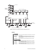
3 2/6/8 Hr 2/6/8 Hr MAIN MONITOR DISPLAY HIGH RESOLUTION *2,6,or 8 Hr 120 Hr 12 Hr 168 Hr 16 Hr 180 Hr 18 Hr 240 Hr 24 Hr 360 Hr 48 Hr 480 Hr 72 Hr 600 Hr 84 Hr 720 Hr 96 Hr 960 Hr RESET ACTIVITY DETECTION ALL CH TO HIGH RESOLUTION REDUCED FLICKER * 2/6/8 HR FOR NTSC/EIA MODEL MULTIPLEXERS, 3 HR FOR PAL/ CCIR MODELS. REMAINING RECORD SPEEDS DEPEND UPON VCR MODEL. Figure 11.
NO CHANGE - This is a pass-through selection in case you unintentionally hit the +/button. This is not an undo button. Alarm Inputs Refer to the Alarms section for an explanation of normally closed and normally open operation. Dwell Rates Sets the sequence dwell rate for all cameras. To set individual dwell rates for cameras, refer to the Sequence Setup section. Activity Detection ENABLED/DISABLED - Turns activity detection on or off for all video inputs.
Date Format Sets the format for displaying the date on the main monitor. Password Enables or disables password control to access programming menus. Front Panel Control Enables or disables the front panel buttons to operate the multiplexer. In either mode you can access programming menus. Main Monitor Display Select ALARMS, ACTIVITY, or ALARMS/ACTIVITY if you want the main monitor to switch to cameras that have alarms or activity detection.
RECORD SETUP (DISPLAY/RECORD BUTTON) To program the VCR recording parameters: 1. Press the DISPLAY/RECORD button for approximately three seconds. Type the password, if requested. The Record Setup menu appears. 2. The currently selected menu item blinks. 3. Use the arrow buttons to move between items on the screen. 4. When the menu item you desire is highlighted (blinking), press the +/- button to cycle through the options to select the one you want.
NORMAL REC. SPEED ALARM REC.
CUSTOM VCR SETUP (DISPLAY/RECORD BUTTON) NOTE: For proper recording, the switching rate of the multiplexer must match that of the VCR. If they do not match, the VCR may skip frames or record duplicate frames. To program the advanced VCR parameters: 1. Press the DISPLAY/RECORD button for approximately three seconds. The Record Setup menu appears. 2. Make sure the VCR Type in the Record Setup menu is set to CUSTOM. 3. The currently selected menu item blinks.
CAMERA SETUP (CAMERA BUTTONS) To program a camera input: 1. Press the desired CAMERA button for approximately three seconds. Type the password, if requested. The Camera menu appears. A video insert appears that shows what the camera is viewing. This is useful to make sure you have selected the correct camera and to see what effect there is on the video when you select a menu option. 2. The currently selected menu item blinks. 3. Use the arrow buttons to move between items on the screen. 4.
Activity Detection A camera can be set to respond or not to respond to motion. If enabled, select SET DETECTION MASK to define what part of the camera’s viewing field will be monitored for motion. 5. To program another camera, press the button for that camera. Repeat steps 2-4. 6. When you have completed all the changes you want to make, go to EXIT. 7. Press the +/- button to exit the programming mode.
7. Turn activity boxes on or off. To turn on all activity boxes, use the arrow buttons to choose SET ALL. Press the +/button. All boxes will contain a symbol as shown in Figure 16. The multiplexer will monitor motion in those boxes. To turn off all activity boxes, use the arrow keys to choose CLEAR ALL. Press the +/button. All boxes will be blank. To turn on or off an individual box, use the arrow keys to select the box. Press +/button to toggle a box on or off.
GROUP 1 2 3 4 QUAD (2x2) 04 04 04 04 NINE (3x3) 04 04 Figure 17. Camera Sequence Menu HELP MENU The Help menu is accessed from any other menu. 1. 2. Use the up and down arrow buttons in any menu to highlight HELP. Press the +/- button. The Help menu appears. HELP BUTTON DISP/REC SETTING VCR SPEED & ALARM QUICK SETUP MONITOR SETUP +/– - SINGLE PRESS MODIFY DOUBLE PRESS CHANGE EDIT DIRECTION HOLD BUTTONS TO ENTER/EXIT THEIR ASSOCIATED MENU USE ARROWS TO NAVIGATE Figure 18.
PROGRAMMING THE 4-CAMERA DISPLAYS ( NOTE: All active cameras may be sequenced in one location of a 4-, 9-, or 16camera display mode. While in a multiple-camera display mode, use the arrow buttons to move the on-screen bar to the camera location for sequencing. Press the sequence button to initiate sequencing of all active cameras. Refer to the Operation Guide table also. BUTTON) You can program four groups of four cameras each. Each of the four groups can be programmed to include any four cameras.
PROGRAMMING MENU DEFAULTS Table E. Programming Menu Defaults Menu System Setup Item Time Display Title Display Normal Record Speed Alarm Record Speed Main Monitor Display Reset All Video Terminations To Reset All Alarm Inputs To Normally Reset All Seq Dwell Rates To Reset Activity Detection All Ch To Advanced System Setup Date Format Password System Password Front Panel Control Main Monitor Display Responds To Spot Monitor Display Responds To Camera Types Unit ID Comm.
TROUBLESHOOTING If you have difficulty operating your system, run through the following checklist to see if you can solve the problem. 1. Are the keyboard switches set properly? 2. Is the equipment wired properly? 3. Are the menu options in the multiplexer(s) and server set properly? 4. Has the multiplexer been set to the correct mode using the DISPLAY/RECORD button? 5. The main monitor will display multiple screen images. The spot monitor displays full screen views only. 6.
RESET To reset the multiplexer: 1. Unplug the power cord. 2. Press and hold the VIEW button on the front panel of the multiplexer while you plug the power cord into an electrical outlet. When the Initialization Menu appears, release the VIEW button. The monitor will indicate PLEASE WAIT and begin a 20-second countdown. When the countdown has been completed, the Initialization Menu will disappear, all programming menus will be at their default settings, and the multiplexer will be ready for use. 3.
REGULATORY NOTICES Note: This equipment has been tested and found to comply with the limits of a Class A digital device, pursuant to part 15 of the FCC rules. These limits are designed to provide reasonable protection against harmful interference when the equipment is operated in a commercial environment. This equipment generates, uses, and can radiate radio frequency energy and, if not installed and used in accordance with the instruction manual, may cause harmful interference to radio communications.