
Manual
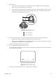
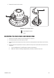
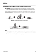
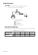
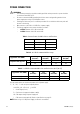
Table Of Contents

50 C3473M-C (10/10)
POWER CONNECTION
Use the formula below to calculate the power cord and power supply.
“L”, “R”, “VA”, “I” shall satisfy the inequality below.
10.8 V DC
≤ VA - 2 (R x I x L) ≤ 16 V DC
L = Cord length (m or ft)
R = Resistance of copper wire (Ω/m or Ω/ft}
VA = DC output voltage of power supply unit
I = DC current consumption (A). Refer to Specifications on page 52.
NOTE: When using a 12 V DC power supply, the heater is unavailable.
WARNINGS:
• The following connections should be made by qualified service personnel or system installers
in accordance with NEC 725-51.
• Be sure to connect the GND (grounding) lead of the camera and grounding terminal of the
power supply when using a 24 V AC power source.
• Shrinking the cable-entry seal is a onetime procedure. Do not shrink the cable-entry seal until
the unit is functioning.
• Only connect to a 24 V AC or 12 V DC Class 2 power supply.
• The voltage supplied to the camera should be as follows:
– 24 V AC: Between 19.5 V AC and 28 V AC
– 12 V DC: Between 10.8 V DC and 16 V DC
Table C. Camera Power Cord Wire Colors and Functions
Wire Color 24 V AC 12 V DC
Brown 24 V AC (L) Positive
Blue 24 V AC (N) Negative
Green/Yellow To GND —
Table D. 24 V AC Recommended Wire Gauge
Copper Wire Size (AWG)
#24
(0.22 mm
2
)
#22
(0.33 mm
2
)
#20
(0.52 mm
2
)
#18
(0.83 mm
2
)
Length of Cable (approx.)
m20 30 45 75
ft 66 100 150 250
Table E. 12 V DC Recommended Wire Size and Resistance (68 °F [20 °C])
Copper Wire Size (AWG)
#24
(0.22 mm
2
)
#22
(0.33 mm
2
)
#20
(0.52 mm
2
)
#18
(0.83 mm
2
)
Resistance (Ω/m) 0.078 0.050 0.03 0.018
Resistance (Ω/ft) 0.024 0.015 0.009 0.005