
Manual
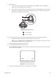
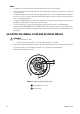
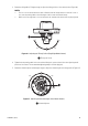
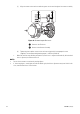
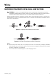
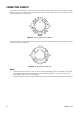
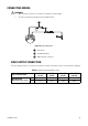
Table Of Contents

C3473M-C (10/10) 43
3. Rotate the tilting table (±75-degree range) to adjust the tilting position of the camera (refer to Figure 36).
NOTES:
• This lens can also be rotated in the reverse direction, but the image azimuth is reversed. In such a
case, turn the panning table to the 180-degree side to correct the azimuth image.
• When used at an angle that is close to horizontal, the shadow of the dome cover may be projected.
Figure 36. Adjusting the Tilting Position (Day/Night Model Shown)
4. Tighten both the panning table lock screw and the tilting lock screws on both sides after adjusting the tilt
position of the camera. The recommended tightening torque is 0.59 N
.
m (6 k
g
f
.
cm).
5. Rotate the azimuth adjuster (±100-degree range) to adjust the azimuth angle of the image (refer to Figure 37).
Figure 37. Adjusting the Azimuth Angle (Color Model Shown)
ì
Tilting Lock Screw
ì
Azimuth Adjuster
75°75°
LOCK
TOP
100°100°