
Manual
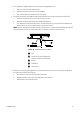
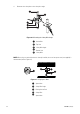
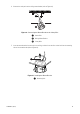
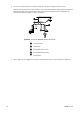
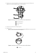
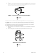
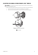
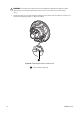
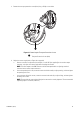
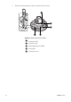
Table Of Contents

C3473M-C (10/10) 39
3. Remove the transport protection screw (blue) using a Phillips screw driver.
Figure 31. Removing the Transport Protection Screw
4. Adjust the camera angle (refer to Figure 32 on page 40):
a. Connect a monitor for adjustment (for example, a small LCD [not supplied]) to the monitor output
connector, and adjust the camera angle while watching the monitor.
NOTE: The video output to the BNC connector will be interrupted while an adjusting monitor is
connected to the monitor output connector.
b. Loosen the panning lock screw, rotate the camera head horizontally to adjust panning, and then tighten
the panning lock screw.
c. Loosen the two tilting lock screws, rotate the camera head vertically to adjust tilting, and then tighten
the tilting lock screws.
NOTE: The panning lock screw and the tilting lock screw must be securely tightened. The recommended
tightening torque is 0.59 N·m (0.44 lbf·ft).
ì
Transport Protection Screw (blue)