
Manual
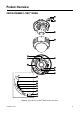
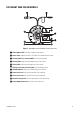
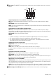
Table Of Contents
18 C3473M-C (10/10)
ì
Tilting Lock Screw: Locks the tilt position.
î
Tilt Adjusting Table: Adjust the azimuth angle of the image.
ï
Panning Table: Rotate this table to adjust the panning angle of the camera.
ñ
Video Output Cable
ó
Power Cord
r
Inner Dome
s
Enclosure
t
Panning Lock Screw: Fixes the panning table.
u
Focus Lock Knob: Locks the focal point.
~í
Zoom Lock Knob: Locks the zoom point.
~â
Camera Fixing Screw: Fixes the attachment on the camera body.
~ä
Monitor Output Connector: Connects the monitor for adjustment to this output connector.
~ã
Right Button [(RIGHT), FAR]: Moves the cursor to the right, selects the mode and adjusts some levels.
~å
Left Button [(LEFT), NEAR]: Moves the cursor to the left, selects the mode and adjusts some levels.
~ç
Up Button [(UP)]: Moves the cursor upward and selects items in the setup menu.
~é
Down Button [(DOWN), ABF1]: Moves the cursor downward and selects items in the setup menu.
~è
Setting Button [(SET), ABF2/MENU]: Confirms the setting contents.
~ê
Heater Output Connector: Connects to the heater unit.
~ë
ABF Operation Indicator: Indicates the status of ABF operation.