® CM9760-IRC Infrared VCR Controller Installation/ Operation Manual C544M (2/98) Pelco • 3500 Pelco Way, Clovis • CA 93612-5699 USA • www.pelco.
CONTENTS Section Page 1.0 GENERAL .................................................................................................. 3 1.1 IMPORTANT SAFEGUARDS AND WARNINGS ............................... 3 2.0 DESCRIPTION .......................................................................................... 4 2.1 GENERAL FEATURES ...................................................................... 5 2.2 SAMPLE SYSTEM ............................................................................ 6 3.
1.0 GENERAL 1.1 IMPORTANT SAFEGUARDS AND WARNINGS Prior to installation and use of this product, the following WARNINGS should be observed. 1. Installation and servicing should only be done by Qualified Service Personnel and conform to all Local codes. 2. Only use replacement parts recommended by Pelco. 3. After replacement/repair of this unit’s electrical components, conduct a resistance measurement between line and exposed parts to verify the exposed parts have not been connected to line circuitry.
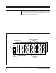
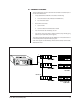
2.0 DESCRIPTION The Pelco 9760-IRC VCR Controller provides remote control of most VCRs equipped with an infrared receiver for controlling standard functions: play, record, stop, fast-forward, rewind, and pause. Eject control depends on the VCR model. This reduces the need for modifications to VCRs. DB9 OUTPUT CONNECTIONS (FEMALE) RS-422 INPUT PORT (MALE) POWER RS-422 OUTPUT PORT (FEMALE) COMMUNICATION CARD CONTROL CARDS Figure 1.
2.1 GENERAL FEATURES The Pelco 9760-IRC is housed in a rack frame and connects to one Sercom port on the rear of the CM9760-CC1. • • A fully populated Pelco 9760-IRC unit consists of the following: a. One communication card (interfaces with CM9760-CC1) b. Four VCR control cards Each control card controls: a. Up to 32 VCRs b. Up to four different VCR brands and/or models • Up to 128 VCRs can be controlled by one unit.
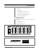
2.2 SAMPLE SYSTEM A typical system installation involving the CM9760-IRC might include: a. CM9760-CC1 e. Monitors b. CM9760-IRC f. Cameras c. CM9760-KBD g. CM9760-MXBs d. VCRs Other Pelco products can be added according to system requirements.
3.0 INSTALLATION To install the Pelco Infrared VCR Controller, proceed as follows: 1. Set the baud. 2. Set the start address. 3. Connect the CM9760-IRC to the CM9760-CC1 host. 4. Connect additional IRC units in daisy-chain fashion. 5. Connect VCRs to the Video Matrix Bay (CM9760-MXB). 6. Connect the IR control cables to the VCRs. Each step listed above is detailed below: 3.
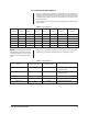
3.1.1 Setting the Baud NOTE: The operating baud must Bauds of 2400, 4800, 9600, and 19200 are available. The communication protocol uses eight data bits, one stop bit, and even parity. match the baud rate set in the .SCP Communications File for the CM9760-CC1. The baud is set using DIP switches 1 and 2 according to Table A. Table A. Baud Settings DIP Switch 2 DIP Switch 1 Baud ON ON 2400 ON OFF 4800 OFF ON 9600 OFF OFF 19200 3.
3.2.1 Setting the Start Address Each Pelco CM9760-IRC unit requires a six-bit start address. The start address is configured using the DIP switches on the communication card (see Figure 5: DIP switches). Each control card occupies one address space. An IRC unit occupies four address spaces (if there are only two control cards in the unit, it still occupies four address spaces). The start address of an IRC unit is set with the DIP switches on the communication card per Table B. Table B.
3.3 CONNECTING THE CM9760-IRC TO THE CM9760-CC1 HOST Each CM9760-IRC has two RS-422 ports; one labeled IN (male) and the other OUT (female). To connect a CM9760-IRC to the CM9760-CC1 host, connect a SerCom port on the host to the IN RS-422 port on the IRC. The data pin connections are shown below in Figure 7.
3.3.1 Connecting the CM9760-IRC to a CM9760-CC1 Host via Serial GPI A CM9760-IRC can be daisy-chained from a serial GPI already connected to a SerCom port of a CM9760-CC1 (CPU). The wiring is the same as for Section 3.3. Connect the RS-422 OUT port of the serial GPI to the RS-422 IN port of the IRC (refer to Figure 8). CM9760-CC1 SERCOM PORTS (FEMALE) (ANY SERCOM PORT) Figure 8. Connecting IRCs in Sequence 3.
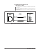
3.5 CONNECTING VCRs TO THE VIDEO MATRIX BAY (CM9760-MXB) VCRs must be connected to the CM9760-MXB (Video Matrix Bay). Two standard coaxial cables are needed: (1) One to run from the VIDEO OUT port on the back of the VCR to the desired IN port on the VMB. (2) The other to run from the VIDEO IN port on the VCR to the desired OUT port on the Video Matrix Bay. VCR (REAR VIEW) CM9760-MXB VIDEO MATRIX BAY INPUT PORTS (UP TO 16 CARDS, 16 PORTS PER CARD) OUTPUT PORTS (1 CARD, 16 PORTS PER CARD) Figure 10.
3.6 VCR CONTROL SIGNAL OUTPUTS An IRC has up to 32 D9 female output connections numbered J1 to J32, each able to control four VCRs (refer to Figure 6). Every DB9 output supports four IR control cables. Each IR control cable controls the functions of a single VCR. The wiring for each DB9 output is shown below in Table D. Table D.
4.0 SPECIFICATIONS Electrical Specifications Operating Voltages: 120 or 230 VAC 50/60 Hz.
NOTES Pelco Manual C544M (2/98) 15
5.0 WARRANTY AND RETURN INFORMATION WARRANTY Pelco will repair or replace, without charge, any merchandise proved defective in material or workmanship for a period of one year after the date of shipment. Exceptions to this warranty are as noted below: • Five years on FT/FR8000 Series fiber optic products. • Three years on Genex® Series products (multiplexers, server, and keyboard).