I N S TA L L AT I O N / O P E R AT I O N ® DX9200HDDI Series IDE Video Storage Unit C637M-B (10/03)
CONTENTS Section Page REGULATORY NOTICES ...................................................................................................................................................................................................... 3 RADIO AND TELEVISION INTERFERENCE ................................................................................................................................................................. 3 IMPORTANT SAFEGUARDS AND WARNINGS ....................................
REGULATORY NOTICES This device complies with part 15 of the FCC Rules. Operation is subject to the following two conditions: (1) this device may not cause harmful interference, and (2) this device must accept any interference received, including interference that may cause undesired operation. RADIO AND TELEVISION INTERFERENCE This equipment has been tested and found to comply with the limits of a Class B digital device, pursuant to part 15 of the FCC rules.
IMPORTANT SAFEGUARDS AND WARNINGS 1. Read these instructions. 2. Keep these instructions. 3. Heed all warnings. 4. Follow all instructions. 5. Do not use this apparatus near water. 6. Clean only with dry cloth. 7. Do not block any ventilation openings. Install in accordance with the manufacturer’s instructions. 8. Do not install near any heat sources such as radiators, heat registers, stoves, or other apparatus (including amplifiers) that produce heat. 9.
DESCRIPTION The DX9200HDDI video storage unit is one of the components of the DX9000 system. The storage unit contains up to 14 IDE hard disk drives for storing video information from the DX9000 recorder. Up to four IDE storage units can be connected to a recorder. The storage unit uses redundant arrays of independent disks (RAID) technology. Level 5 or Level 5+1 is available.
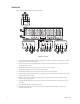
FRONT VIEW Figure 1 shows the features on the front of the IDE storage unit. EXIT CTRL 1 ENG o POWER o C- F EXIT CTRL 1 ENC o POWER o C-F Figure 1. Front View 1. Panel: Use the features of this panel to view the configuration of the RAID or to enter the environment menu. You must lower this panel to remove or add hard drives. 2. Hard drive trays: There are 14 hot-swappable hard drive trays. Each holds an IDE hard drive.
11. Up arrow/Quit button: Used in conjunction with the Controller and ENC buttons. Press to scroll through the information on the LCD display, to move through each menu, or to go back to the previous menu. 12. Down arrow/Info button: Used in conjunction with the Controller and ENC buttons. Press to scroll through the information on the LCD display or to move through each menu. 13. Select/C-F button: Use to enter the option you have selected or to change the temperature display from celsius to fahrenheit.
INSTALLATION Make sure the following parts are supplied with the storage unit. 1 2 2 2 2 4 12 4 Video Storage Unit with IDE hard drives Power cords (1 USA standard and 1 European standard) External SCSI cables Active terminators (for connecting to SCSI channels) Brackets 6 Screws, M4 x .250-inch, pan head Adjustable support rails 6 Screws, 8-32 x .375-inch, pan head with washers Screws, 10-32 x .375-inch, flat head Screws, 10-32 x .
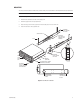
MOUNTING The storage unit can be placed on a flat surface, such as a shelf, or it can be installed in a 19-inch (48.26 cm) wide equipment rack. NOTE: Allow one rack unit (1.75 inches or 4.5 cm) of space above the storage unit for air circulation. To install the storage unit in an equipment rack: 1. Attach the two brackets to each side of the storage unit. 2. Attach the support rails to the equipment rack. 3. Place the storage unit onto the support rails. It should easily slide in and out of the rack.
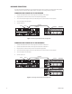
HARDWARE CONNECTIONS There are five hardware configurations. You can connect one storage unit to one recorder, one storage unit to two recorders, two storage units to one recorder, three storage units to one recorder, or four storage units to one recorder. CONNECTING ONE STORAGE UNIT TO ONE RECORDER 1. Connect a SCSI cable from Host A on the storage unit to Channel A on the recorder. 2. Plug the power cords into the units and into a universal power supply (UPS). 3.
CONNECTING TWO STORAGE UNITS TO ONE RECORDER 1. Connect a SCSI cable from Host A on Storage A to Channel A on the recorder. 2. Connect a SCSI cable from Host A on Storage B to Channel B on the recorder. 3. Plug the power cords into the units and into a universal power supply (UPS). 4. Turn on the three power supplies on the rear of each storage unit. You can turn them on in any sequence. 5. Turn on each storage unit’s main power. 6. Turn the recorder on.
CONNECTING THREE STORAGE UNITS TO ONE RECORDER 1. Connect a SCSI cable from Host A on Storage A to Channel A on the recorder. 2. Connect a SCSI cable from Host A on Storage B to Channel B on the recorder. 3. Connect a SCSI cable (DX9200HDDI-LCBL) from the Host A Out port on Storage A to the Host A In port on Storage C. 4. Plug the power cords into the units and into a universal power supply (UPS). 5. Turn on the power supplies on the rear of each storage unit. You can turn them on in any sequence.
CONNECTING FOUR STORAGE UNITS TO ONE RECORDER 1. Connect a SCSI cable from Host A on Storage A to Channel A on the recorder. 2. Connect a SCSI cable from Host A on Storage B to Channel B on the recorder. 3. Connect a SCSI cable (DX9200HDDI-LCBL) from the Host A Out port on Storage A to the Host A In port on Storage C. 4. Connect a SCSI cable (DX9200HDDI-LCBL) from the Host A Out port on Storage B to the Host A In port on Storage D. 5.
OPERATION The storage unit has been preconfigured to operate using RAID Level 5 or RAID Level 5+1 technology. Pelco recommends RAID Level 5+1. In Level 5+1, a hot spare drive is included. If a hard drive is removed or fails, the redundant data, on the remaining drives, relocates automatically to the hot spare and begins the reconstruction process without user intervention.
TROUBLESHOOTING What do I do when the voltage warning LED illuminates red and an alarm sounds? This happens when the output DC voltage is under 4.5V or over 5.5V, and under 10.2V or over 13.8V. The ENC global fault LED also illuminates. Press the Exit/Alarm reset button to stop the alarm. A low beep continues to sound. There may be a problem with the voltage of the power outlet. Call technical support for assistance.
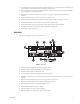
SERVICE HOW TO REPLACE A FAN The fans are hot-swappable. The spare part number for the fan is DX9200HDDI-FAN. THUMBSCREW HANDLE Figure 9. Replacing a Fan 1. Loosen the thumbscrew. 2. Pull the screw to lift the handle. 3. Pull out the defective fan. 4. Slide the new fan into the unit. 5. Tighten the screw. HOW TO REPLACE A POWER SUPPLY The power supplies are hot-swappable. The spare part number for the power supply is DX9200HDDI-PWR. HANDLE THUMBSCREW Figure 10. Replacing a Power Supply 1.
HOW TO CHANGE FROM RAID 5 TO RAID 5+1 To change a RAID 5 configuration to a RAID 5+1 configuration, you must add a hot spare hard drive. A hot spare hard drive becomes the replacement hard drive when a hard drive fails in the RAID 5+1 configuration. Make sure you have the appropriate spare drive from Pelco: DX9000DRV-I120 or DX9000DRV-I250. Because the hard drives are hot-swappable, you do not have to shut down the power before adding or removing them. WARNING: Handle the hard drive with extreme care.
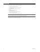
POWER CONNECTOR 40-PIN ATA CABLE CONNECTOR LEVER RELEASE LEVER ATA CABLE CONNECTOR PORT JUMPER POWER PORT PHILLIPS SCREWS TRAY WITH HARD DRIVE Figure 11.
WARRANTY AND RETURN INFORMATION WARRANTY Pelco will repair or replace, without charge, any merchandise proved defective in material or workmanship for a period of one year after the date of shipment. Exceptions to this warranty are as noted below: • Five years on Pelco manufactured cameras (CC3500/CC3600/CC3700 and MC3500/ MC3600 Series); two years on all other cameras. • Three years on Genex® Series (multiplexers, server, and keyboard) and 090 Series Camclosure® Camera System.
® World Headquarters 3500 Pelco Way Clovis, California 93612 USA USA & Canada Tel: 800/289-9100 Fax: 800/289-9150 International Tel: 1-559/292-1981 Fax: 1-559/348-1120 www.pelco.