I N S T A L L A T I O N ® Endura™ SP04-140 Dual-Input Video Encoder C613M-A (5/05)
Contents Regulatory Notices . . . . . . . . . . . . . . . . . . . . . . . . . . . . . . . . . . . . . . . . . . . . . . . . . . . . . . . . . . . . . . . . . . . . . . . . . . . . . . . . . . . . . . . . . . . . . . . . . . . .4 Description . . . . . . . . . . . . . . . . . . . . . . . . . . . . . . . . . . . . . . . . . . . . . . . . . . . . . . . . . . . . . . . . . . . . . . . . . . . . . . . . . . . . . . . . . . . . . . . . . . . . . . . . . .5 Before You Begin . . . . . . . . . . . . . . . . . . . . .
List of Illustrations 1 2 3 4 5 6 7 8 9 10 11 12 13 14 15 16 17 18 19 20 Product Serial Number Label . . . . . . . . . . . . . . . . . . . . . . . . . . . . . . . . . . . . . . . . . . . . . . . . . . . . . . . . . . . . . . . . . . . . . . . . . . . . . . . . . . . . . . . .6 SP04-140 Desktop Placement. . . . . . . . . . . . . . . . . . . . . . . . . . . . . . . . . . . . . . . . . . . . . . . . . . . . . . . . . . . . . . . . . . . . . . . . . . . . . . . . . . . . . . . .
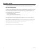
Regulatory Notices This device complies with Part 15 of the FCC Rules. Operation is subject to the following two conditions: (1) this device may not cause harmful interference, and (2) this device must accept any interference received, including interference that may cause undesired operation. RADIO AND TELEVISION INTERFERENCE This equipment has been tested and found to comply with the limits of a Class B digital device, pursuant to Part 15 of the FCC Rules.
Description The SP04-140 is a special version of the single-input NET5301T video encoder. It is a high-performance, dual-stream, dual-input video encoding unit. Its main function is to convert live analog video from two cameras into dual MPEG-4 video streams. It transmits these streams over an Ethernet network to other Endura™ system components.
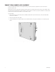
PRODUCT SERIAL NUMBER LABEL PLACEMENT Product serial number labels help Pelco’s Product Support identify your system and its factory configuration in case the SP04-140 or its components require service. A label citing your product’s serial number is attached to the bottom panel of the SP04-140. Because rack mounting or other installation options may obscure the factory-applied label, two additional labels are provided.
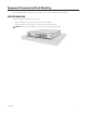
Equipment Placement and Rack Mounting The SP04-140 can be placed on a flat surface, such as a desktop; mounted to a wall; or mounted into an equipment rack. DESKTOP MOUNTING To place the SP04-140 on a flat surface, such as a desktop: 1. Make sure the rubber feet are installed on the unit to prevent surface damage. 2. Position the unit to allow for cable and power cord clearance at the front and rear panels. WARNING: Do not place the SP04-140 unit on its side; the unit could fall over and cause damage.
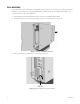
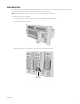
WALL MOUNTING The SP04-140 can be mounted to a wall using the optional WM5001-4U wall mount system. You can mount up to four SP04-140, NET5301T, and NET5301R units, in any combination, in a fully expanded WM5001-4U (one WM5001-4U with up to three WM5001-4UEXP expansion units). To mount the SP04-140 to a wall using the WM5001-4U: 1. Install the WM5001-4U and any WM5001-4UEXP expansion units (refer to the WM5000 installation manual). 2. Insert the SP04-140 into the desired wall mount unit.
RACK MOUNTING Any combination of SP04-140, NET5301T, and NET5301R units can be mounted together in the optional RK5000PS-5U rack mount kit, up to 12 units. Each unit plugs directly into a power connector in the rack and is powered by the rack. NOTE: The RK5000PS-5U only supplies power. It does not provide a dock for any other unit connectors. To install the SP04-140 into a rack mount kit: 1. Install the RK5000PS-5U rack mount kit into the rack (refer to the RK5000PS-5U installation manual). 2.
PELCO BADGE ORIENTATION The Pelco badge on the front panel of the SP04-140 can be rotated in quarter turns. If you install the unit on a flat surface, the Pelco badge will be turned the wrong way. To rotate the Pelco badge: 1. 2. 3. 4. Use the Pelco badge rotation sticker that came with the unit. Attach the middle portion of the rotation sticker to the badge. Press firmly with your thumb and rotate the badge to its correct position. Remove the rotation sticker from the badge. PELCO BADGE Figure 7.
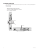
Connections Familiarize yourself with the SP04-140 rear panel before connecting any equipment to the unit. TERMINATION SWITCH FOUR-PIN POWER TWO-PIN POWER VIDEO IN (1) VIDEO IN (2) AUDIO SWITCH AUDIO IN PTZ CONTROL (RS-422) RELAY CONTROL AUDIO OUT ALARM INPUT Figure 8. SP04-140 Rear Panel CONNECTING VIDEO INPUTS The SP04-140 offers two analog video inputs. The unit automatically detects the video standard (PAL or NTSC) and accepts both color and black-and-white analog video at both inputs.
Before installing the SP04-140, make sure the distance from the unit to the video device is less than the maximum distance for the coaxial cable. Refer to Table A for maximum video coaxial cable distances. Table A.
CONNECTING AUDIO The SP04-140 supports half-duplex, bidirectional audio (one direction at a time). It transmits audio and video signals simultaneously. This lets you control a loudspeaker or other audio equipment, such as a door intercom system, at the monitored location. The unit supports both microphone and line input levels. Microphones are usually not powered; they have weaker signals that must be amplified. Line inputs usually have stronger, powered signals that have already been amplified.
CONNECTING A PTZ DEVICE, RELAY, AND ALARMS The SP04-140 incorporates a 16-pin terminal block to support the following: • PTZ device, such as a dome camera, using the Pelco D protocol (RS-422) • Relay control, either normally open or normally closed • Up to three alarm inputs, supervised or unsupervised, using any combination of high and low signals The terminal block has tension clamps instead of screw terminals. Use a small screwdriver to open the clamp for a particular lead.
CONNECTING A PTZ DEVICE (PELCO D PROTOCOL) NOTE: To connect a Coaxitron PTZ device, refer to Connecting Video Inputs The SP04-140 supports camera control using Pelco D protocol (RS-422) for a PTZ device. You can connect only one serial PTZ device to a video encoder. The default Pelco D device address is 0. When the SP04-140 receives a camera control command, it transmits that command to the PTZ device.
Refer to Table C when installing the PTZ device. It lists the serial port settings that the SP04-140 supports. Table C. Serial Port Options and Defaults Setting Options Default Data rate (bits per second) 110, 300, 1200, 2400, 4800, 9600, 19200, 38400, 57600, 115200, 230400 Data bits 5, 6, 7, 8 Parity None, Odd, Even Stop bits 1, 2 2400 8 None 1 CONNECTING A RELAY DEVICE The SP04-140 has an output for triggering an external device. It supports both momentary and continuous relay operation.
CONNECTING ALARMS The SP04-140 offers three alarm inputs for external signaling devices, such as door contacts or motion detectors. Each encoder supports either all normally open or all normally closed devices. If your installation requires mixed devices, install another SP04-140, NET5301T, or a NET5301R video decoder. Then connect the normally open devices to one unit and the normally closed devices to the other unit.
Figure 15 illustrates the wiring configuration for supervised alarm inputs. NORMALLY CLOSED NORMALLY OPEN 1 KΩ 1 KΩ 1 KΩ 1 KΩ UNUSED INPUTS MUST ALSO BE WIRED 1 KΩ UNUSED INPUTS MUST ALSO BE WIRED 1 KΩ Figure 15. Supervised Alarm Input Wiring Unsupervised Alarms When an alarm is configured as an unsupervised alarm, the SP04-140 only triggers an alarm when the normal alarm state (open or closed) changes. Figure 16 illustrates the alarm and no alarm conditions of an unsupervised alarm input.
Alarm Connections Figure 18 shows how to wire the video encoder to an alarm (refer to Table B for the specific connector pin assignments). Figure 18. Connecting Alarms CONNECTING POWER The SP04-140 video encoder is designed to operate from either a 12 VDC or a 24 VAC power supply. It automatically senses power type and polarity (DC). The SP04-140 can be powered from many sources: • NET5301PS power supply connects directly to the four-pin connector on the SP04-140 rear panel.
Use Table E to help identify the necessary wire gauge and maximum cable distance. This table applies to two-conductor solid copper wire. (Reduce distance by 10% for stranded copper wire.) These maximum distances are based on a maximum allowable voltage drop of 10%. Table E. Recommended Wire Gauge and Maximum Wiring Distances Maximum Distance Wire Gauge 20 AWG (0.5 mm2) 12 VDC 24 VAC 89 ft (27 m) 356 ft (108 m) 18 AWG (1.0 mm2) 141 ft (42 m) 566 ft (172 m) 16 AWG (1.
Operation Refer to the WS5000 operation manual for details on how to access and configure the SP04-140 video encoder. FRONT PANEL INDICATORS UNIT STATUS NETWORK CONNECTOR NETWORK STATUS NETWORK ACTIVITY VIDEO PRESENCE CONFIGURATION/ RESET BUTTON Figure 20. SP04-140 Front Panel Pelco badge (power) The Pelco badge glows blue when the unit has power. Unit status Unit status is indicated by one of the following three colors: Green Amber Red The unit is functioning normally.
CONFIGURATION/RESET BUTTON Use the recessed configuration/reset button at the top of the front panel to access the following modes: Table F. Configuration/Reset Button Functions and Indicators Mode Function Unit Status Indicator Light Configuration Initiates system configuration. • Flashing amber when entering this mode • Solid amber when selected Reboot Restarts the unit.
Troubleshooting If the following instructions fail to solve your problem, contact Pelco Product Support at 1-800-289-9100 or 1-559-292-1981 for assistance. Access the properties windows for the SP04-140 video encoder on the WS5050 workstation (refer to the WS5000 operation manual).
Specifications MODEL NUMBER SP04-140 Dual-input network video server that encodes video, audio, and control data for transmission over an IP network SUPPLIED ACCESSORIES Mating Connectors One 16-pin, one 2-pin SYSTEM Processor PowerPC® 405EP Operating System Linux® User Interface Remote operation via WS5050 or VCD5000 VIDEO/AUDIO Video Standards NTSC/PAL/EIA/CCIR composite Video Coding MPEG-4 Video Streams 2, simultaneous Video Resolutions 4CIF 2CIF CIF QCIF NTSC 704 x 480 704 x 240 352 x 2
VIDEO ACTIVITY DETECTION Zones 3 plus background zone Zone Types Any shape, user-definable in 16 x 16 pixel blocks Sensitivity Adjustable AUXILIARY INTERFACES Serial Pelco D (RS-422); uses 4 of 16 pins on terminal block connector Terminal Block Connector 16-pin: Pelco D (RS-422), 3 alarm inputs, 1 relay output FRONT PANEL INDICATORS/FUNCTIONS Network RJ-45, 10/100 BaseT Power Blue Status Green, amber, red Network Link/Speed Amber, red Network Activity Green Video Green, red Configurati
STANDARDS/ORGANIZATIONS • Pelco is a member of the MPEG-4 Industry Forum • Pelco is a member of the Universal Plug and Play (UPnP) Forum • Pelco is a member of the Universal Serial Bus (USB) Implementers Forum • Pelco is a contributor to the International Standards for Organization/Electrotechnical Commission (ISO/IEC) Joint Technical Committee 1 (JTC1), “Information Technology,” Subcommittee 29, Working Group 11 • Compliance, ISO/IEC 14496 standard (also known as MPEG-4) • Compliant with International Tele
PRODUCT WARRANTY AND RETURN INFORMATION WARRANTY Pelco will repair or replace, without charge, any merchandise proved defective in material or workmanship for a period of one year after the date of shipment. Exceptions to this warranty are as noted below: • Five years on FT/FR8000 Series fiber optic products and the following fixed camera models: CC3701H-2, CC3701H-2X, CC3751H-2, CC3651H-2X, MC3651H-2, and CC3651H-2X.
® Worldwide Headquarters 3500 Pelco Way Clovis, California 93612 USA USA & Canada Tel: 800/289-9100 Fax: 800/289-9150 International Tel: 1-559/292-1981 Fax: 1-559/348-1120 www.pelco.