® KBD960/KBR960 Series Desktop Intelligent Keyboard/M Installation/ Operation Manual C1519M-D (3/06) Pelco World Headquarters • 3500 Pelco Way, Clovis, CA 93612-5699 USA • www.pelco.
CONTENTS Section Page REGULATORY NOTICES .................................................................................. 6 IMPORTANT SAFEGUARDS AND WARNINGS ............................................... 7 DESCRIPTION .................................................................................................. 8 MODELS .................................................................................................... 8 READING THIS MANUAL .........................................................
ADVANCED OPERATION ................................................................................ 30 PRESETS ................................................................................................. 30 CREATING PRESETS ...................................................................... 30 RECALLING PRESETS .................................................................... 30 DELETING PRESETS ...................................................................... 30 PATTERNS ...................
LIST OF ILLUSTRATIONS Figure 1 2 3 4 5 6 7 8 9 10 11 12 13 14 15 16 17 18 19 20 21 22 23 24 25 26 27 28 29 30 31 32 33 34 35 36 37 38 39 40 41 42 43 4 Page KBD960/KBR960 ................................................................................. 9 Connecting to the CM6800 ................................................................ 11 Enter Setup PIN ................................................................................. 12 Setup Mode ...................................................
LIST OF TABLES Table A B C D E F G H I J K L M N O Q R S U V W X Y Page Function Key Defaults .......................................................................... 15 Main Menu 1 ........................................................................................ 17 Main Menu 2 ........................................................................................ 17 Monitor Menu ....................................................................................... 18 Camera Menu 1 .............
REGULATORY NOTICES This equipment has been tested and found to comply with the limits of a Class B digital device, pursuant to part 15 of the FCC rules. These limits are designed to provide reasonable protection against harmful interference in a residential installation. This equipment generates, uses, and can radiate radio frequency energy and, if not installed and used in accordance with the instructions, may cause harmful interference to radio communications.
IMPORTANT SAFEGUARDS AND WARNINGS 1. Read, keep, and follow these instructions. 2. Heed all warnings. 3. There are no user-serviceable parts inside this unit. Only authorized service personnel may open the unit. 4. Installation and servicing should only be done by qualified service personnel and conform to all local codes. 5. WARNING: To reduce the risk of fire or electric shock, do not expose this unit to rain or moisture if this unit is designed for indoor use only. 6.
DESCRIPTION The KBD960/KBR960 Keyboard includes Pelco’s proprietary M protocol, allowing it to be used with all M devices, such as Pelco’s latest matrix switch – the CM6800. You can program the keyboard, and you can create and execute macros. You have access to effective monitoring procedures for any CCTV application. You can assign simple or complex functions to many of the keys. This allows you to configure the keyboard to suit a specific monitoring environment.
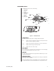
KEYBOARD LAYOUT The KBD960 keyboard consists of the following: 1. 2. 3. 4. 5. 6. 7. 8. 9. LCD Display Icon Keys Keypad Function Keys Control Keys Lens Keys Joystick Turbo Key Escape Key 9 2 1 ICON KEYS LCD DISPLAY 7 ESCAPE KEY JOYSTICK 8 TURBO KEY FUNCTION KEYS (F1-F24) 4 6 3 KEYPAD 5 LENS KEYS CONTROL KEYS 00891 KBD960 KBR960 Figure 1. KBD960/KBR960 LCD DISPLAY The LCD is a four-line display. Each line displays different information.
CONTROL KEYS These keys are used for the following functions: Step backward through available camera selections. Step forward through available camera selections. Select and execute macros. Rcl: Recall previous selections. Alt: Reserved for future use. Prst: Recall preset. Lock: Reserved for future use. LENS KEYS You can use these keys to control cameras equipped with motorized zoom lenses and motorized pan and tilt units. These keys are sometimes used to activate other functions.
INSTALLATION The following items are supplied: • • • • • KBD960/KBR960 keyboard KBD-PS-1 universal power supply Two 25 ft (7.6 m) straight RJ-45 cables (one with ferrite) 10 blank labels and 10 punched LEXAN decal overlays One power cord (either US-320-C5, UK-320-C5, AU-320-C5, EU-320-C5) CONNECTING TO THE CM6800 NOTE: Communication to the keyboards is RS-485.
SETUP MODE You can configure the KBD960 in the Setup Mode. You can do the following: • • • • • • • Create a Personal Identification Number (PIN) for entering the Setup Mode. Create a PIN that provides access to features on the Define Menu. Calibrate the joystick. Adjust the display brightness. Set the data transmission speeds for the keyboard’s three COM ports. Define the function keys. Select a host port. The default setup PIN is 1234. You can change it in the Setup Mode.
Advance Setup 2 Setup Pin Confirm Define Pin Confirm CREATING A SETUP PIN **** **** **** **** The factory settings for the KBD960 include the default setup PIN 1234. Follow these steps to change the default PIN: DEF NUM 00898 1. Select 2. Select and/or to locate Advance Setup 2. 3. Select and/or to choose Setup PIN. 4. Select 5. Advance the cursor to the confirm row, select ADV from Setup Mode. Figure 6. Advance Setup 2 select 6.
ADJUSTING THE DISPLAY BRIGHTNESS LCD BRIGHTNESS SETUP 00899 1. Select 2. Select to make the display brighter or 3. Select and then LCD from Setup Mode. to make the display dimmer. Figure 7. LCD Brightness Setup . You can also adjust the display brightness by selecting LCD from the Define Menu. Refer to the Operation section of this manual. CONFIGURING THE COM PORTS Advance Setup 1 COM1 COM2 COM3 Local Address None (Host) None None 1 1. Select 2. Select and/or 3.
CONFIGURING THE FUNCTION KEYS NOT DEFINED NUMx ESC BKSPACE ENTER DEFINE KEY DEFINE 1. Select from Setup Mode to switch to the key define mode. 2. Press a function key you want to configure. If the key is already defined, its assigned function is shown. If not, “Def = NOT DEFINED” appears on the LCD screen. 3. Select and/or 4. Select to choose a function. 5. Select DEF NUM and enter the define number. 6. Select DEF NUM . 7. Select PLEASE ENTER A KEY DEF NUM 00901 Figure 9.
OPERATION This section describes the operation of a CM6800 System using the KBD960 keyboard. Before you begin operating the KBD960, make sure you have completed the following: 1. Connections have been made and initial power-up has been completed. 2. CM6800 setup files have been programmed. 3. PINs have been set up to allow logging on, access to the setup functions, and access to the Define Menu.
ACCESSING THE KBD960 MENUS 1. Set DIP switch 2 OFF. 2. Enter the number of the monitor and then press 3. Press . and the Main Menu 1 icons appear. Table B. Main Menu 1 1 MAIN MENU 1 1 Select to bring up the Monitor Menu. If you enter a number before selecting this icon, the monitor number changes to that number. MUX GPI PRST LOG OFF Select to bring up the Camera Menu.
Table D. Monitor Menu 1 MONITOR MENU 1 Select to request the previous logical monitor number in the system and to grant control of the monitor if it is available. The logical monitor number range is 1-9999. Select to request the next logical monitor number in the system and to grant control of the monitor if it is available. The logical monitor number range is 1-9999. 00906 Figure 14. Monitor Menu This icon indicates whether or not you have control of the monitor.
Table F. Camera Menu 2 3 CAMERA MENU 2 1 1 4 5 6 7 3 Select to send an AUX 3 set command to the selected camera. When you release the key, a clear command is sent. 4 Select to send an AUX 4 set command to the selected camera. When you release the key, a clear command is sent. 5 Select to send an AUX 5 set command to the selected camera. When you release the key, a clear command is sent. 6 Select to send an AUX 6 set command to the selected camera.
Table H. MUX Menu 2 1 MUX MENU 2 1 MUX Select to send a MUX PIP command to the selected multiplexer. 00910 Figure 18. MUX Menu 2 Select to send a MUX 4-camera command to the selected multiplexer. Select to send a MUX 9-camera command to the selected multiplexer. Select to send a MUX 16-camera command to the selected multiplexer. Select to bring up MUX Menu 1. Select to return to Main Menu 1. Table I.
Table J. GPI Menu 1 1 GPI MENU 1 1 GPI GPI GPI MTRY 1 2 3 4 00912 Figure 20. GPI Menu 1 MTRY Select to set the current GPI to the input value. Select to request control of the selected GPI and send a message to gather information about the status of the auxiliaries within the GPI. You have control if this icon is highlighted. If this icon is highlighted, the auxiliary control method is momentary. If it is not highlighted, the auxiliary control method is latching.
Table L. Preset Menu 1 PRESET MENU 1 PRST PRST Select to send a PRESET CALL command to the current camera. Select to send a PATTERN START command to the current camera. You can enter a number to initiate a specific pattern. PRST 00914 Figure 22. Preset Menu Select to send a ZONE SCAN ON command to the current camera and display the “Zone On” text. When this text is displayed, you can select this icon again to send a ZONE SCAN OFF command, which displays the “Zone Off” text.
Table N. Sequence Menu 1 SEQUENCE MENU 1 Select to request the previous logical sequence number in the system and grant control of the sequence if it is available. SEQ Select to request the next logical sequence number in the system and grant control of the sequence if it is available. SEQ 00916 Figure 24. Sequence Menu SEQ This icon shows whether or not you have control of the selected sequence. If the sequence is highlighted, you have control.
Table Q. Define Preset Menu 1 DEFINE PRESET MENU 1 DEF PRST PRST DEL PRST 00919 Figure 27. Define Preset Menu DEL Select to send a set preset command and a preset label to the current camera. A preset number is required prior to selecting this icon. Reserved for future use. Select to return to the Define Menu. Table R. D efine Zone Menu 1 DEFINE ZONE MENU 1 DEF Select to send a set zone command to the current camera. Select to return to the Define Menu. 00920 Figure 28.
Table U. Database Menu DATABASE MENU Select to send the keyboard’s key configuration to another keyboard. You must enter the local device address of the second keyboard. This is only sent to a device on the same bus as the keyboard. DEF 00923 Figure 31. Database Menu Select to receive another keyboard’s key configuration database. You must enter the local device address of the second keyboard. This is only sent to a device on the same bus as the keyboard. Select to return to the Define Menu.
ACCESSING THE CM6800 MAIN PROGRAMMING MENU 1. Select 2. Enter your Define PIN. 3. Select 4. Select DEF . MENU . PGM . The following screen appears on your monitor. PELCO VIDEO SWITCHER MODEL CM6800 PASSWORD TO MAIN MENU ******* SCRATCHPAD SEQUENCE RETURN 00619 Figure 32. Password Screen 5. Enter your password (default is 2899100). The Main Programming Menu appears.
DIAGNOSTIC MODE To activate the Diagnostic Mode set DIP switch 1 ON. This mode allows the following tests: DIAGNOSTIC MODE vX.XX 00925 Figure 34. Diagnostic Mode Menu • • • • LCD test Keyboard test Serial Input/Output (SIO) test DIP Switch test TESTING THE DISPLAY LCD TEST G0 G1 G2 1. Select while in the Diagnostic Mode. 2. Select G0 to test graphic page 0. 3. Select G1 to test graphic page 1. 4. Select G2 to test graphic page 2. 5. Select T0 to test the text page. 6.
TESTING THE SERIAL PORTS SIO TEST COM1 COM2 This test is reserved for factory use only. COM3 00928 Figure 37. SIO Test TESTING THE DIP SWITCHES DIPSWITCH TEST 00000001 1. Select 2. Beginning with switch 2, set each switch ON while observing the display. . 00929 Figure 38.
SELECTING MONITORS You can select up to eight monitors. There are several ways you can select monitors. MAIN MENU 1 1. Enter the monitor number (1-8). 2. Press or select . The monitor number appears next to on the keyboard LCD. MONITOR MENU 1. Select from Main Menu 1. 2. Cycle through the available monitors using You can also enter a monitor number and press NOTE: F22 is the “enter” default, but you can assign this function to one of the other function keys. and/or . or select .
OPERATING PTZ CAMERAS The controls for PTZ cameras are located on the right-hand side of the keyboard. The proportional joystick allows variable speed drives. It gives you full control over the pan and tilt movements, from minimum to maximum speed. Speed is proportional to the amount by which you move the joystick from its center location. Press while moving the joystick to enable high speed operation. The joystick only provides directional control when a fixed speed PTZ camera is installed.
ADVANCED OPERATION PRESETS NOTE: Presets are only possible when receivers or pan/tilt units have preset capability. A preset camera position is a set of parameters which define pan, tilt, zoom, and focus adjustments. There are four ways you can recall a preset camera position: • • • • Manually using the keyboard Automatically as the result of an alarm condition From a macro command From a sequence command CREATING PRESETS There are 64 available presets.
PATTERNS A pattern is a user-defined, viewable camera path with a definite beginning and end. You must create a pattern before the time-out clock expires. For example,‚ the timer is 60 seconds. If you are using a Spectra II®‚ the timer is 1.5, 3, or 6 minutes. (See the section on Pattern Length.) You will not see the time-out clock on the monitor. CREATING PATTERNS 1. Move the joystick to a desired starting point. 2. Select 3. Select DEF from Main Menu 2. Refer to Table C. .
PATTERN LENGTH You can set three time values for single pattern lengths and three corresponding time values for two half-pattern lengths from the Esprit™ Programming Menu. The single pattern lengths are 1.5 minutes, 3 minutes, and 6 minutes. The corresponding halfpattern lengths are .75 minutes, 1.5 minutes, and 3 minutes. Follow these steps to bring up the programming menu: 1. Go to Define Menu 2. Refer to Table C. 2. Enter 95 and press the Prst side of . The monitor displays the Preset Label Menu.
ZONES A zone is a user-defined space to which a label is attached and a camera is associated. The camera used at the time the zone boundaries are defined is associated with the zone. The zone label appears on the selected monitor after zone definition if you move the camera within the defined zone. You can define and associate up to eight zones with the same camera. A priority level (1-8, with 8 being the highest) is assigned to each zone.
NOTE: To create zones when using Spectra III cameras, you must enable the zone label display in the Spectra III menus. CREATING ZONES 1. Move the joystick to Point A. 2. Select 3. Select 4. from Main Menu 2 and enter your PIN, if necessary. DEF . Enter a zone priority level (1-8) and select again. The icon becomes highlighted signaling the start of zone creation. “Edit label. Ack-set for left edge. Pan right. Press 81 & F5 for right edge.” appears on the monitor. 5.
PARTIAL ZONE OVERLAP Partial zone overlap occurs when the end of one zone overlaps with the beginning of another zone. The zone with the highest priority level appears at all times. Refer to Figure 41. ZONE A BEGINS ZONE B BEGINS THIS PORTION OF ZONE B DOES NOT APPEAR BECAUSE ZONE A OVERLAPS IT AND HAS A HIGHER PRIORITY LEVEL. THE REMAINDER OF ZONE B DOES APPEAR. ZONE A PRIORITY 5 ZONE A ENDS ZONE B ENDS ZONE B PRIORITY 2 00932 Figure 41.
EMBEDDED ZONES An embedded zone is a zone that is between two other zones. In Figure 42, Zone C is embedded between Zone A and Zone B. An embedded zone is not seen unless its priority level is higher than the priority level of the other zones. Since Zone C has a priority level of 6, portions of Zone A and Zone B are not seen.
MACROS A macro is a sequence of commands or steps. When you run a macro, the steps programmed into that macro are performed. Macros can be run manually or automatically. Automatic operation can be the result of alarms or the reaching of specific times and dates. If you want to start a macro, make sure no other keyboard has control of the PTZ on the monitor that you want the macro to start on. When a macro completes all its steps, it stops and only runs again if restarted.
SEQUENCE You can select up to 16 sequences. Camera number and title, sequence status, and time/date appear on the monitor when you select a sequence. To set up a sequence, you must bring up the CM6800 Programming Main Menu from the KBD960 or use the CM6800-MGR Program Manager. There can be 72 steps in a sequence. A sequence can consist of various commands (patterns, presets, random scan, frame scan, stop scan) and auxiliaries (global auxiliary on/off or camera auxiliary on/off).
OPERATING RELAYS To operate relays from a KBD960 keyboard, you must know which GPI to call and which auxiliary (AUX) to select on the keyboard. You can cascade two relay units. Each relay unit has eight GPIs. Relay Unit 1 has a GPI range of 1-8, and Relay Unit 2 has a GPI range of 9-16. Refer to Tables W and X. There are two ways you can operate relays from the KBD960. ACTIVATING RELAYS USING F12 Follow these steps to activate a momentary relay: 1. 2. 3. Go to Main Menu 1.
Table W. Relay Unit 1 GPI 1 2 3 4 5 6 7 8 ASSOCIATED AUX 1 9 17 25 33 41 49 57 1 2 10 18 26 34 42 50 58 2 RELAY CONTACTS 3 4 5 6 11 12 13 14 19 20 21 22 27 28 29 30 35 36 37 38 43 44 45 46 51 52 53 54 59 60 61 62 3 4 5 6 7 15 23 31 39 47 55 63 7 8 16 24 32 40 48 56 64 8 71 79 87 95 103 111 119 127 7 72 80 88 96 104 112 120 128 8 Table X. Relay Unit 2 NOTE: In Relay Unit 2, GPIs 9-16 are associated with the physical relays (1-64) on the back of the unit.
MULTIPLEXER CONTROL You can also control multiplexers with the KBD960 keyboard. You can connect multiplexers to any input. Refer to the CM6800 Installation/Operation Manual (C1515M) for instructions on setting the multiplexers for keyboard control. Follow these steps to control multiplexers: 1 1. 1 Enter a MUX input number and press . Each MUX input is associated with a camera input. Figure 43 shows MUX 1 being controlled. MUX GPI PRST LOG OFF 2. Figure 43. MUX Control Menu Select MUX .
VIDEO LOSS The loss of a video signal may alert you or trigger an alarm. The alarm is reported back to the keyboard. Using the video loss function, faulty cameras can be disabled if necessary. ALARMS Alarms can be armed or disarmed from the KBD960 keyboard using the System 6800 menus. RESETTING TRIGGERED ALARMS A triggered alarm causes a continuous tone. The alarm volume can be altered using the level control on the bottom of the keyboard. You cannot turn on an alarm that has been muted.
APPENDICES LOG OFF LOG OFF JSTK JOYSTICK ADJUST 4 AUX 4, RELAY 4 4-CAMERA MUX YES LOG OFF YES ADV ADVANCE MENUS 5 AUX 5, RELAY 5 9-CAMERA MUX NO LOG OFF NO SERIAL PORT TEST 6 AUX 6, RELAY 6 16-CAMERA MUX PIN SETUP/DEFINE PIN SEND KEYBOARD SETUP 7 AUX 7, RELAY 7 LIVE MUX SAVE SELECTION RECEIVE KEYBOARD SETUP 8 AUX 8, RELAY 8 MUX CAMERA CONTROL DEL DELETE G0 TEST GRAPHIC PAGE 0 RESET ALARM SEQ SEQUENCE MENU MORE MENU G1 TEST GRAPHIC PAGE 1 RESET ALL ALARMS PRST CAME
ENTER SETUP PIN SETUP MODE vX.XX JSTK LCD ADV Advance Setup 1 KEY DEFINE NOT DEFINED NUMx ESC BKSPACE ENTER DEFINE PLEASE ENTER A KEY COM1 COM2 COM3 Local Address None (Host) None None 1 DEF NUM JOYSTICK SETUP xxx xxx (xxx, xxx) xxx xxx Advance Setup 2 Setup Pin Confirm Define Pin Confirm **** **** **** **** DEF NUM LCD BRIGHTNESS SETUP 00936 Appendix B.
DIAGNOSTIC MODE vX.XX LCD TEST G0 G1 G2 T0 DIAGNOSTIC MODE vX.XX KEYBOARD TEST vX.XX PLEASE ENTER A KEY Joystick Position — (xxx, xxx) DIAGNOSTIC MODE vX.XX SIO TEST COM1 COM2 COM3 DIAGNOSTIC MODE vX.XX DIPSWITCH TEST 00000001 00937 Appendix C.
MAIN MENU 1 1 1 LOGOFF MENU MAIN MENU 2 1 1 Logoff? MUX GPI LOG OFF PRST YES 1 1 NO PRESET MENU MAC 1 SEQ DEF 1 PRST MACRO MENU PRST 1 GPI MENU 1 1 MAC 1 1 MAC GPI CAMERA MENU 1 SEQUENCE MENU GPI 1 MTRY 1 2 3 4 1 1 GPI MENU 2 1 2 1 1 SEQ 1 SEQ GPI DEFINE MENU 1 CAMERA MENU 2 5 6 7 8 1 1 1 ALARM MENU 3 4 5 6 7 1 8 1 PIN LCD DEFINE MENU 2 MONITOR MENU 1 1 PIN 1 1 MUX MENU 1 1 1 DEF 1 MUX PRST LCD MENU MUX MUX MENU 2 1 1 DEFI
SPECIFICATIONS ELECTRICAL Input Voltage: 100-240 VAC, 50/60 Hz Power Consumption: 10 watts Communications: RS-485 Operating Distance: 4,000 feet (1,219 m) on 24 AWG wire Connectors: Two 8-pin, RJ-45 connectors (female); RS-485 serial ports One 4-pin, RJ-45 connector (female); RS-232 serial (diagnostic) port Two 6-pin RJ-45 connectors (female) not used OPERATIONAL Joystick: Proportional Display: Four-line, backlit LCD for programming and control LCD Menu Display: Eight icon keys for LCD menu se
PRODUCT WARRANTY AND RETURN INFORMATION WARRANTY Pelco will repair or replace, without charge, any merchandise proved defective in material or workmanship for a period of one year after the date of shipment. Exceptions to this warranty are as noted below: Five years on FR/FT/FS Series fiber optic products and TW3000 Series unshielded twisted pair transmission products. Three years on Genex® Series products (multiplexers, server, and keyboard).
® Worldwide Headquarters 3500 Pelco Way Clovis, California 93612 USA USA & Canada Tel: 800/289-9100 Fax: 800/289-9150 International Tel: 1-559/292-1981 Fax: 1-559/348-1120 www.pelco.