INSTALLATION/OPERATION 400 Series Flat Panel LCD Monitors C2927M-A (1/06)
Contents Important Safety Instructions . . . . . . . . . . . . . . . . . . . . . . . . . . . . . . . . . . . . . . . . . . . . . . . . . . . . . . . . . . . . . . . . . . . . . . . . . . . . . . . . . . . . . . . . . . . .4 Regulatory Notices . . . . . . . . . . . . . . . . . . . . . . . . . . . . . . . . . . . . . . . . . . . . . . . . . . . . . . . . . . . . . . . . . . . . . . . . . . . . . . . . . . . . . . . . . . . . . . . . . . . .5 Description . . . . . . . . . . . . . . . . . . . . . . . . . . . .
Important Safety Instructions 1. Read these instructions. 2. Keep these instructions. 3. Heed all warnings. 4. Follow all instructions. 5. Do not use this apparatus near water. 6. Clean only with dry cloth. 7. Do not block any ventilation openings. Install in accordance with the manufacturer’s instructions. 8. Do not install near any heat sources such as radiators, heat registers, stoves, or other apparatus (including amplifiers) that produce heat. 9.
Regulatory Notices This device complies with Part 15 of the FCC Rules. Operation is subject to the following two conditions: (1) this device may not cause harmful interference, and (2) this device must accept any interference received, including interference that may cause undesired operation. RADIO AND TELEVISION INTERFERENCE This equipment has been tested and found to comply with the limits of a Class B digital device, pursuant to Part 15 of the FCC Rules.
Description The 400 Series high performance LCD monitors are designed specifically for the security industry and provide high quality display of video or computer signals via multiple inputs. These 15-, 17-, and 19-inch monitors use a color, thin film transfer (TFT) active matrix LCD panel that automatically adapts to the appropriate input resolution.
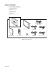
PACKAGE CONTENTS 1 1 1 1 1 1 1 2 1 15-, 17-, or 19-inch TFT LCD monitor VGA cable with 15-pin, D-sub connector US standard power cable EU standard power cable DVI cable USB cable (Type A to B) Remote control unit AA batteries Installation/Operation manual VGA CABLE WITH 15-PIN, D-SUB CONNECTOR TFT LCD MONITOR INSTALLATION OPERATION MANUAL REMOTE CONTROL UNIT 2 AA BATTERIES US STANDARD POWER CABLE DVI CABLE EU STANDARD POWER CABLE USB CABLE (TYPE A TO B) Figure 1.
Installation The monitor can be placed on any flat surface (desk or table), or it can be rack mounted or wall mounted. NOTE: Only use a recommended rack mount or wall mount kit, such as the PMCL-RM15, PMCL-RM17, PMCL-RM19, or PMCL-WM. To rackmount or wall-mount the monitor, follow the instructions supplied with the mount kit. Refer to manual C2220M for the rack mount kit instructions or C2219M for the wall mount kit instructions.
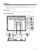
1. AC IN: This can be connected to a 100-240 VAC, 50/60 Hz source. 2. DC OUT: This connection can output 12 VDC, 0.5 A (continuous), 50/60 Hz. 3. DC IN: This can be connected to an external 12 VDC, 5 A source. 4. VGA IN: This can be connected to the VGA cable (supplied). 5. DVI IN: This can be connected to the DVI cable (supplied). 6. USB: This is the USB-A 2.0 downstream port. It can be used to connect to such peripherals as a USB camera or USB key. 7. USB: This is the USB-A 2.0 downstream dual port.
VIDEO AND POWER CONNECTIONS Refer to Figure 2 for video, audio, power, and other connections. 1. Connect the video cable. (Refer to Table A for video coaxial requirements.) a. Connect video cables as follows, depending on the input source. • • • • b. For composite, connect to the BNC video input labeled VIDEO 1 IN on the back panel of the monitor. If the installation requires a second video input, connect a video cable to the BNC video input labeled VIDEO 2 IN. (Inputs are auto-terminating.
PMCL400 2.0 DVR CAMERA S-VIDEO IN OUT AUDIO IN AUDIO L R L R AUDIO SOURCE AUDIO OUT DVR OUT CAMERA VIDEO 1 IN IN OUT DVR VIDEO 2 CAMERA Figure 3. Looping Operation: One Monitor with External Video Equipment PMCL400 PMCL400 PMCL400 2.0 2.0 2.
Operation INSTALLING REMOTE CONTROL BATTERIES PRESS AND SLIDE TO REMOVE Figure 5. Battery Installation Refer to Figure 5 for the following procedure. 1. Open and remove the battery cover on the back of the remote control. 2. Install two AA size batteries (supplied). Match the + and – signs on the batteries to the signs on the battery compartment. 3. Close the battery cover. Make sure the lock snaps closed. WARNING: 12 • Dispose of batteries in a designated disposal area.
FRONT PANEL CONTROLS CH Figure 6. Front Panel Controls 1. This button selects the input signal and swaps the main and PIP displays when PIP is active. 2. This button decreases the value of a selected menu item and accesses the brightness control when no PIP or menu is active. It can reposition PIP when PIP is active. 3. This button increases the value of a selected menu item, and it enables or disables PIP when no menu is active. 4. This button moves the highlighter downward through a menu.
REMOTE CONTROL FUNCTIONS PIP SWAP LOCATE CH VOL Figure 7. Remote Control Functions 1. This button turns on or off power to the monitor. 2. This button selects the previous channel. 3. This button selects the next channel. 4. This button increases the audio volume. 5. This button decreases the audio volume. 6. This button moves the PIP location to the next location (upper left, upper right, lower right, lower left, middle). 7.
OSD CONTROL MENUS Unless otherwise noted, the menus are the same for the PMCL415, PMCL417, and PMCL419. Also, since different options are available for different input types, some menus have a video mode and a VGA mode. Some options may be unavailable and are grayed out. NOTE: There is no reset feature to return the monitor to factory defaults. To use the menus: 1. Press the menu button to access the Main menu. 2. Use the up and down arrow buttons to highlight a selection. 3.
VIDEO MENU (VGA MODE) VIDEO MENU Contrast AUDIO MENU Brightness SCREEN MENU Color SOURCE MENU Tint OPTION MENU Sharpness EXIT MENU Noise Reduction weak 50 50 Contrast Brightness Return Menu Figure 9. Video Menu (VGA Mode) If PIP is active in VGA mode, these controls affect PIP and not the Main Display. Video Menu (VGA Mode) Field Definitions Contrast: Adjusts white level of the video screen image. Brightness: Adjusts black level of the video screen image.
SCREEN MENU (VGA MODE) VIDEO MENU AUDIO MENU SCREEN MENU SOURCE MENU OPTION MENU EXIT MENU Clock 50 Display Mode Aspect Clock H Position V Position Phase Smoothing Auto Sync Color Temperature DEFAULT Return Menu H Position 7 V Position 49 Phase 10 Smoothing 2 Auto Position 9300K 7500K 6500K Default Figure 12. Screen Menu (VGA Mode) Screen Menu (VGA Mode) Field Definitions Clock: Adjusts the horizontal size of the screen image. H Position: Moves the screen image left or right.
SOURCE MENU (VGA MODE) VIDEO MENU AUDIO MENU Main Display Source: VGA PIP Display source: OFF Return Menu VGA DVI VIDEO-1 VIDEO-2 SVIDEO SCREEN MENU SOURCE MENU OPTION MENU VIDEO-1 VIDEO-2 SVIDEO OFF EXIT MENU Figure 14. Source Menu (VGA Mode) Source Menu (VGA Mode) Field Definitions Main Display Source: Select one: VGA, DVI, VIDEO-1, VIDEO-2, SVIDEO. PIP Display source: Select one: VIDEO-1, VIDEO-2, SVIDEO, OFF. (Some choices will be grayed out depending on your Main Display Source selection.
MENU DEFAULT VALUES Refer to the following default values if you need to manually return the monitor to the factory settings.
Supported Input Modes 20 Mode Resolution H Freq (kHz) V Freq (Hz) 0 720 x 350 31.469 70.087 1 640 x 480 31.469 59.940 2 640 x 480 35.000 66.667 3 640 x 480 37.861 72.809 4 640 x 480 37.500 75.000 5 720 x 400 31.469 70.087 6 800 x 600 35.156 56.250 7 800 x 600 37.879 60.317 8 800 x 600 48.077 72.188 9 800 x 600 46.875 75.000 10 1024 x 768 48.363 60.004 11 1024 x 768 60.023 75.
Specifications MODELS PMCL415 PMCL417 PMCL419 15-inch (381 mm) active TFT LCD monitor 17-inch (432 mm) active TFT LCD monitor 19-inch (483 mm) active TFT LCD monitor GENERAL LCD Panel Pixel Array PMCL415 PMCL417, PMCL419 Panel Aspect Ratio PMCL415 PMCL417, PMCL419 Viewing Area PMCL415 PMCL417 PMCL419 Pixel Pitch PMCL415 PMCL417 PMCL419 Brightness PMCL415 PMCL417 PMCL419 Contrast Ratio Backlight Type Panel Lamp Life Viewing Angle (H/V) PMCL415 PMCL417 PMCL419 Tilt Display Colors PMCL415, PMCL417 PMCL419 Re
PHYSICAL Dimensions PMCL415 PMCL417 PMCL419 Unit Weight PMCL415 PMCL417 PMCL419 Shipping Weight PMCL415 PMCL417 PMCL419 13.7" W x 11.7" H x 3.0" D (34.70 x 29.8 x 7.5 cm) 15.0" W x 13.4" H x 3.2" D (38.1 x 34.1 x 8.0 cm) 16.6" W x 14.7" H x 3.3" D (42.1 x 37.4 x 8.3 cm) 10.1 lb (4.6 kg) 13.1 lb (5.9 kg) 15.1 lb (6.9 kg) 14.0 lb (6.4 kg) 18.0 lb (8.2 kg) 20.0 lb (9.
PRODUCT WARRANTY AND RETURN INFORMATION WARRANTY Pelco will repair or replace, without charge, any merchandise proved defective in material or workmanship for a period of one year after the date of shipment. • Three years on Genex ® Series products (multiplexers, server, and keyboard). If a warranty repair is required, the Dealer must contact Pelco at (800) 289-9100 or (559) 292-1981 to obtain a Repair Authorization number (RA), and provide the following information: 1. Model and serial number 2.
Worldwide Headquarters 3500 Pelco Way Clovis, California 93612 USA USA & Canada Tel: 800/289-9100 Fax: 800/289-9150 International Tel: 1-559/292-1981 Fax: 1-559/348-1120 www.pelco.