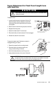
® Installation/Operation 300 Series Camclosure® Integrated Camera System C2408M-F (4/03) Pelco • 3500 Pelco Way • Clovis, CA 93612-5699 USA • www.pelco.
CONTENTS Section Page IMPORTANT SAFEGUARDS AND WARNINGS . . . . . . . . . . . . . . . . . . . . . . . . . . . . . . . . . . . . . . . . . . . 3 DESCRIPTION . . . . . . . . . . . . . . . . . . . . . . . . . . . . . . . . . . . . . . . . . . . . . . . . . . . . . . . . . . . . . . . . . . . . . 3 INSTALLATION . . . . . . . . . . . . . . . . . . . . . . . . . . . . . . . . . . . . . . . . . . . . . . . . . . . . . . . . . . . . . . . . . . . . . 3 PREPARE WALL OR CEILING . . . . . . . . . . . . . . . . . . .
IMPORTANT SAFEGUARDS AND WARNINGS 1. Read these instructions. 2. Keep these instructions. 3. Heed all warnings. 4. Follow all instructions. 5. Do not block any ventilation openings. Install in accordance with the manufacturer’s instructions. 6. Do not install near any heat sources such as radiators, heat registers, stoves, or other apparatus (including amplifiers) that produce heat. 7. Only use attachments/accessories specified by the manufacturer. 8.
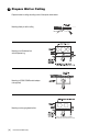
1 Prepare Wall or Ceiling Prepare the wall or ceiling according to one of the options shown below. Mounting directly to wall or ceiling Mounting to a 4S electrical box with 404 plaster ring Mounting to ICS300-COND conduit adapter (not supplied) Mounting to a two-gang electrical box 6-32 X .
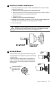
2 Connect Video and Power 1. Some indoor installations do not require a heater. If the installation does not require a heater, disconnect the heater wiring. a. Remove the cover with the supplied 1/8-inch hollow screwdriver bit. b. Remove the camera from the mounting bracket and unplug the four-pin heater connector in the base. The connector has orange, red, and black wires. c. Reinstall the camera. d. Reseat the O-ring on the cover and reinstall the cover. 2.
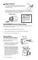
LOCKING RINGS 4 Adjust Camera Turn on power to the camera and monitor. Release one or both locking rings, swivel the enclosure until the angle of the camera is correct, and tighten the locking rings. If you have a varifocal lens, remove the cover with the supplied 1/8-inch hollow screwdriver bit. Loosen the focal length and focus locking screws. Adjust according to scene detail. Retighten the screws. Reseat the O-ring on the cover and reinstall the cover.
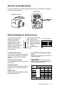
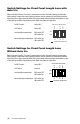
Auto Iris Level Adjustment If you have a varifocal lens or fixed focal length lens with an auto iris, you can adjust the iris level setting to increase or decrease brightness. FIXED LENS VARIFOCAL LENS The high resolution camera with varifocal lens and auto iris is configured at the factory for optimal performance in lighting conditions where auto iris is required. It is also configured with the shutter speed set at 1/60 (NTSC) or 1/50 (PAL) and AGC set at 6 dB of gain.
Switch Settings for Fixed Focal Length Lens with Auto Iris Refer to the switch drawing. The switch is located next to the lens. Automatic backlight compensation (factory setting) is used under varying lighting conditions (such as outdoors) or fixed lighting conditions where there are no bright spots that darken other picture details. Manual backlight compensation is used in fixed lighting conditions to optimize the picture detail when there are bright spots.
Focus Adjustment for Fixed Focal Length Lens with Auto Iris CAUTION Heater elements could be hot! When camera power is on, use caution when adjusting the camera. To adjust the focus: 1. Loosen the locking screw on the bottom of the lens. To loosen the screw, it may be necessary to remove the heater board. Refer to the figure below and the accompanying steps. FOCUS ADJUSTMENT SCREW 2. Move the screw in the slot to bring the picture into focus. 3. Retighten the locking screw. 4.
SPECIFICATIONS Electrical Input Voltage: Power Consumption: Video Connector: 12 VDC or 24 VAC, ±10% Construction: 13 watts or less Finish: Dimensions: BNC Environment: General Pan/Tilt Adjustment: Rating: Manual; 180° pan; 180° tilt Meets NEMA Type 3R standards Operating Temperature: Weight: Heater: Aluminum base and cover, steel camera mounting bracket Gray polyester powder coat 2.71 (diameter) x 7.79 (L) inches (6.88 x 19.
PRODUCT WARRANTY AND RETURN INFORMATION WARRANTY Pelco will repair or replace, without charge, any merchandise proved defective in material or workmanship for a period of one year after the date of shipment. Exceptions to this warranty are as noted below: • Five years on FT/FR8000 Series fiber optic products. • Three years on Genex® Series products (multiplexers, server, and keyboard).
REVISION HISTORY Manual # C2408M C2408M C2408M-A C2408M-B Date 11/99 1/00 3/00 7/00 C2408M-C C2408M-D C2408M-E C2408M-F 1/01 12/01 1/03 4/03 Comments Original version. Revised installation instructions. Added FCC notices. Added varifocal lens. Changed format. Viewing window redesigned, changed icon. Added agency logos for compliance certifications. Revised heater element caution. Manual revised to reflect product design revisions. Revised camera drawings to show new design.