INSTALLATION/OPERATION ® 200 Series Camclosure® Integrated Camera System C2406M-F (4/04)
IMPORTANT SAFEGUARDS AND WARNINGS 1. Read these instructions. 2. Keep these instructions. 3. Heed all warnings. 4. Follow all instructions. 5. Do not block any ventilation openings. Install in accordance with the manufacturer’s instructions. 6. Do not install near any heat sources such as radiators, heat registers, stoves, or other apparatus (including amplifiers) that produce heat. 7. Only use attachments/accessories specified by the manufacturer. 8.
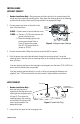
DESCRIPTION The wedge style 200 Series Camclosure® integrated camera system is designed to mount directly to a wall or ceiling. It also can mount to a corner with the ICS200-CM corner mount. The system incorporates a camera and lens package into a small, medium security enclosure.
INSTALLATION The following parts are supplied: 1 1 1 3 3 1 Camclosure integrated camera system Watertight mounting plate 1/8-inch pin-in-hex Allen wrench bit 10-32 x 0.5-inch Phillips screws #10 internal tooth lock washers Hole plug PREPARE MOUNTING SURFACE 1. Remove the cover of the ICS200. Use the screwdriver bit that is provided to loosen the three tamperproof screws, and then lift the cover from the base. 2.
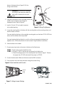
INSTALL BASE WITHOUT CONDUIT 1. Outdoor Installation Only – Bring the power and video wiring for the camera through the wiring hole in the watertight mounting plate. Then fasten the mounting plate to the mounting surface with #8 stainless steel screws (not provided) of the appropriate length. 2. Connect power input wires to the wires in the base of the Camclosure. FOUR-PIN POWER CONNECTOR 24 VAC 24 VAC – Connect power to the red and blue wires. 12 VDC – a.
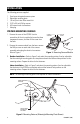
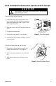
bottom of the base (refer to Figure 5). Pull the wiring inside the base. WARNING: Be careful not to damage the wiring or the connection where the video cable is fastened to the circuit board. 3. Using the screwdriver bit that is provided, remove the conduit cover and plate by unscrewing the tamperproof screw. Refer to Figure 6. 4. Install a 3/4-inch (1.91 cm) conduit connector in the conduit opening. Figure 5. Wiring Plug Removal 5.
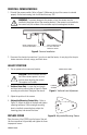
REINSTALL CAMERA MODULE 1. Reinstall the camera module. Refer to Figure 8. Make sure the top of the camera is oriented properly. On the lens housing, look for the label that says TOP. WARNING: To prevent damage to the camera or lens, the camera must be installed in the proper hole of the mounting bracket. If the camera is not installed in the correct hole, the window of the enclosure may be forced against the lens. MOUNT CAMERAS WITH 2.9 AND 3.
ADJUSTMENTS (COLOR CAMERA ONLY) If you have a color camera, it is set up at the factory and normally requires no adjustments. Sometimes, however, adjustments may be necessary. 1. Remove the cover using the supplied 1/8-inch hollow screwdriver bit. 2. Adjust the vertical phase, iris level, focus, or switch settings (refer to procedures below). 3. Replace the cover.
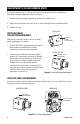
FOCUS ADJUSTMENT FOR FIXED FOCAL LENGTH LENS WITH AUTO IRIS CAUTION Heater elements could be hot! When camera power is on, use caution when adjusting the camera. To adjust the focus, do the following: 1. Loosen the locking screw on the bottom of the lens. To loosen the screw, it may be necessary to remove the heater board. Refer to Figure 14 and the accompanying steps. 2. Move the screw in the slot to bring the picture into focus. 3. Retighten the locking screw. 4.
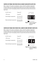
SWITCH SETTINGS FOR FIXED FOCAL LENGTH LENS WITH AUTO IRIS Refer to Figure 15. The switch is located next to the lens. Automatic backlight compensation (factory setting) is used under varying lighting conditions (such as outdoors) or fixed lighting conditions where there are no bright spots that darken other picture details. Manual backlight compensation is used in fixed lighting conditions to optimize the picture detail when there are bright spots.
The high resolution camera with varifocal lens and auto iris is configured at the factory for optimal performance in lighting conditions where auto iris is required. It is also configured with the shutter speed set at 1/60 (NTSC) or 1/50 (PAL) and AGC set at 6 dB of gain.
SPECIFICATIONS General Pan/Tilt Adjustment: Manual; ±10° pan; 5° above horizontal to 20° below horizontal tilt; additional 24° pan adjustment when installing using the adjustable mounting pattern in base Rating: Meets NEMA Type 4 and IP66 standards Construction: Aluminum base and cover, steel camera mounting bracket Finish: Gray polyester powder coat Dimensions Without Watertight Mounting Plate: With Watertight Mounting Plate: Operating Temperature: 3.29 (H) x 3.26 (W) x 6.20 (L) inches (8.36 x 8.
REGULATORY NOTICES FCC Class A (monochrome, EIA cameras only) This equipment has been tested and found to comply with the limits of a Class A digital device, pursuant to part 15 of the FCC rules. These limits are designed to provide reasonable protection against harmful interference when the equipment is operated in a commercial environment.
WARRANTY AND RETURN INFORMATION WARRANTY Pelco will repair or replace, without charge, any merchandise proved defective in material or workmanship for a period of one year after the date of shipment. Exceptions to this warranty are as noted below: • • • • • • • • • • Five years on Pelco manufactured cameras (CC3500/CC3600/CC3700 and MC3500/MC3600 Series); two years on all other cameras. Three years on Genex® Series (multiplexers, server, and keyboard) and 090 Series Camclosure® Camera System.
REVISION HISTORY Manual # C2406M C2406M-A C2406M-B C2406M-C C2406M-D Date 11/99 1/00 2/00 11/00 1/01 1/03 C2408M-E C2408M-F 4/03 4/04 C2406M-F (4/04) Comments Original version. Revised installation instructions. Added FCC notices. Added varifocal lens. Changed format. New camera module design, revised installation instructions. Revised heater element caution. Revised manual for new mounting bracket for camera. Revised camera drawings to show new design. Added instructions for fixed lens with auto iris.
® World Headquarters 3500 Pelco Way Clovis, California 93612 USA USA & Canada Tel: 800/289-9100 Fax: 800/289-9150 International Tel: 1-559/292-1981 Fax: 1-559/348-1120 www.pelco.