INSTALLATION/OPERATION ® 150 Series Camclosure® Integrated Camera System with LowLight™ DSS Technology In-Ceiling Mount C2461M-A (7/03)
CONTENTS Section Page IMPORTANT SAFEGUARDS AND WARNINGS ..................................................................................... 3 WELCOME .......................................................................................................................................... 4 INSTALL THE BACK BOX .................................................................................................................... 5 REMOVE THE LOWER DOME .......................................................
IMPORTANT SAFEGUARDS AND WARNINGS 1. Installation and servicing should be done only by qualified service personnel and conform to all local codes. 2. Unless the unit is specifically marked as a NEMA Type 3, 3R, 3S, 4, 4X, 6, or 6P enclosure, it is designed for indoor use only and must not be installed where exposed to rain and moisture. 3. Use only installation methods and materials capable of supporting four times the maximum specified load. 4.
WELCOME Thank you for purchasing Pelco’s Camclosure® integrated camera system with LowLight™, DSS (digital slow shutter) technology. Your new ICS150 Series in-ceiling dome system includes a highresolution, low light, color camera with auto iris and varifocal lens. The LowLight color camera has extended DSS settings to enhance the low light performance of the camera by automatically adjusting the number of fields of integration.
INSTALL THE BACK BOX REMOVE THE LOWER DOME Loosen the tamper-resistant screws with the supplied 1/8-inch hollow screwdriver bit. Remove the lower dome and place it to the side. INSTALL THE BACK BOX The installation methods for the ICS150 back box include the following: • Attach Directly to a Wall/Ceiling • Attach to a 4S Deep Electrical Box • Install in a Ceiling Tile Select the best method for your installation, and then refer to the following pages for instructions.
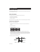
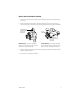
Attach to a 4S Deep Electrical Box Refer to Figure 2 for the following steps. The installation instructions assume that the 4S box was previously installed. 1. Attach adapter plate to the 4S box with the two 8-32 x .750-inch screws supplied. 2. Connect the video cable. 3. Connect the power wires.
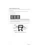
Install in a Ceiling Tile Refer to Figure 3 for the following steps. 1. Cut a hole 3.5 inches (9 cm) in diameter in the ceiling tile for the back box. Use the adapter plate as a template. 2. Punch four screw holes in the ceiling tile. Use the four threaded screw holes in the adapter plate as a template. 3. Attach the back box to the ceiling tile and adapter plate with the four 8-32 x 1.25-inch screws supplied. 4. Replace the ceiling tile. 5. Remove an adjacent ceiling tile and connect the video cable. 6.
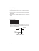
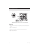
INSTALL THE CAMERA MODULE CHECK HEATER JUMPER The Camclosure is equipped with a heater to defrost the dome. Some installations may not require this heater. If the unit will never be subjected to a frost temperature, you can disable the heater, saving power requirements. To disable the heater, remove the jumper cover from the J1 jumper block (refer to Figure 4). It is recommended that the jumper cover be left in the unit by installing it on one of the jumper pins. CAMERA CONNECTOR J1 JUMPER Figure 4.
INSTALL AND POSITION THE CAMERA 1. Plug the video connector from the camera into the mating connector inside the back box (refer to Figure 4). 2. Position the camera so that the tab on the camera bracket is pointing out of the enclosure, away from the ceiling or wall. Refer to the following illustrations for proper camera installation.
MAKE CAMERA SETTINGS CAUTION: Heater elements could be hot! When camera power is on, use caution when adjusting the camera. This applies to all models. DSS2 DSS1 AGC BLC ON OFF WHITE INDICATES SWITCH SETTING LEVEL PHASE N W ZOOM FOCUS T Figure 5. Default Switch Settings and Location of Camera Adjustments ZOOM/FOCUS 1. Select a field of view by turning the zoom adjustment ring clockwise/counterclockwise. Refer to Figure 5. 2. Tighten the zoom locking screw. 3.
DIGITAL SLOW SHUTTER (DSS) Digital slow shutter slows the picture frame rate and increases the camera sensitivity under low light conditions. Depending on the number of fields of integration the picture will develop a granular appearance and motion may show some lag, resulting in a stereoscopic effect or streaking on fast moving objects. These effects increase as the number of fields of integration increase.
VERTICAL PHASE ADJUSTMENT (24 VAC OPERATION ONLY) When using more than one camera power supply, a brief vertical roll may occur on the monitor when a camera view is switched. To eliminate vertical roll reverse the 24 VAC connections on one camera. If both cameras are connected to the same transformer, this should solve the problem. If reversing the connections does not solve the problem, adjust the phase control by synchronizing, or line-locking, the cameras to one another.
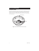
REINSTALL THE DOME AND TRIM RING Place the trim ring and dome over the back box. If the dome has a liner, position the viewing window over the lens of the camera. Tighten the tamper-resistant screws with the supplied 1/8-inch hollow screwdriver bit. Note that the screws are installed at an angle. PRODUCT WARRANTY AND RETURN INFORMATION Figure 6.
SPECIFICATIONS BACKBOX Electrical Input Voltage: Power Consumption: Video Connector: 12 VDC or 24 VAC, ±10%, auto-sensing 13 watts or less BNC General Operating Temperature: -50° to 122°F (-46° to 50°C) De-ices to 25°F (-4°C) Pan/Tilt Adjustment: Manual; 360° pan; 180° tilt Construction: Aluminum with steel camera mounting bracket and polycarbonate dome Finish: White polyester powder coat Dimensions Above Ceiling: 1.75 (H) x 3.50 (W) inches (4.45 x 8.89 cm) Below Ceiling: 2.42 (H) x 5.48 (W) inches (6.
WARRANTY AND RETURN INFORMATION WARRANTY Pelco will repair or replace, without charge, any merchandise proved defective in material or workmanship for a period of one year after the date of shipment. Exceptions to this warranty are as noted below: • • • • • • • • • • Five years on Pelco manufactured cameras (CC3500/CC3600/CC3700 and MC3500/MC3600 Series); two years on all other cameras. Three years on Genex® Series (multiplexers, server, and keyboard) and 090 Series Camclosure® Camera System.
® World Headquarters 3500 Pelco Way Clovis, California 93612 USA USA & Canada Tel: 800/289-9100 Fax: 800/289-9150 International Tel: 1-559/292-1981 Fax: 1-559/348-1120 www.pelco.