
User's Manual


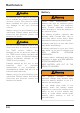
Table Of Contents
- Table of Contents
- 1 Foreword
- 2 Safety First
- 3 Warning Labels
- 4 Parts Identification
- 5 Serial Numbers
- 6 Instruments
- 6.1 Instrument Displays Overview
- 6.2 Thin Film Transistor (TFT) Instrument Display
- 6.2.1 Instrument Panel Layout
- 6.2.2 TFT Display Navigation
- 6.2.3 TFT Themes and Styles
- 6.2.4 Warning Lights
- 6.2.4.1 Engine Management System Malfunction Indicator Light (MIL)
- 6.2.4.2 Low Oil Pressure Warning Light
- 6.2.4.3 Immobiliser/Alarm Indicator Light
- 6.2.4.4 ABS (Anti-Lock Brake System) Warning Light
- 6.2.4.5 Traction Control (TC) Indicator Light
- 6.2.4.6 Traction Control (TC) Disabled Warning Light
- 6.2.4.7 Cruise Control Light
- 6.2.4.8 Triumph Semi Active Suspension (TSAS) Warning Light
- 6.2.4.9 Direction Indicators
- 6.2.4.10 Hazard Warning Lights
- 6.2.4.11 High Beam Button
- 6.2.4.12 Daytime Running Lights (DRL)
- 6.2.4.13 Low Fuel Warning Light
- 6.2.4.14 Tyre Pressure Monitoring System (TPMS) Warning Light (if fitted)
- 6.2.5 Speedometer and Odometer
- 6.2.6 Tachometer
- 6.2.7 Gear Position Display
- 6.2.8 Fuel Gauge
- 6.2.9 Service Interval Announcement
- 6.2.10 Ambient Air Temperature
- 6.2.11 Riding Modes
- 6.2.12 Riding Mode Selection
- 6.2.13 Information Tray
- 6.2.13.1 Warnings
- 6.2.13.2 Trip Meter
- 6.2.13.3 Fuel Status Information
- 6.2.13.4 Tyre Pressure Monitoring System (TPMS) (if fitted)
- 6.2.13.5 Odometer
- 6.2.13.6 Service Interval Announcement
- 6.2.13.7 Triumph Semi Active Suspension (TSAS)
- 6.2.13.8 Screen Contrast
- 6.2.13.9 Style Options
- 6.2.13.10 Coolant Temperature
- 6.2.13.11 Windscreen Adjustment
- 6.2.14 Main Menu
- 6.2.15 Instrument Panel Position Adjustment
- 6.3 Liquid Crystal Display (LCD) Instrument Display
- 6.3.1 Instrument Panel Layout
- 6.3.2 Warning Lights
- 6.3.2.1 Engine Management System Malfunction Indicator Light (MIL)
- 6.3.2.2 Low Oil Pressure Warning Light
- 6.3.2.3 High Coolant Temperature Warning Light
- 6.3.2.4 Immobiliser/Alarm Indicator Light
- 6.3.2.5 ABS (Anti-Lock Brake System) Warning Light
- 6.3.2.6 Traction Control (TC) Indicator Light
- 6.3.2.7 Traction Control (TC) Disabled Warning Light
- 6.3.2.8 Cruise Control Light
- 6.3.2.9 Direction Indicators
- 6.3.2.10 High Beam Switch
- 6.3.2.11 Fog Lights (if fitted)
- 6.3.2.12 Low Fuel Warning Light
- 6.3.2.13 Neutral
- 6.3.2.14 Battery Warning Light
- 6.3.2.15 Tyre Pressure Warning Light (if TPMS is fitted)
- 6.3.2.16 Frost Warning Light
- 6.3.3 Warning and Information Messages
- 6.3.4 Tachometer
- 6.3.5 Motorcycle Status Display Screen
- 6.3.6 Multifunction Display Screen
- 6.3.7 Settings Menu
- 6.3.8 Riding Modes
- 7 General Information
- 7.1 Hand Controls
- 7.1.1 Keyless Ignition (if fitted)
- 7.1.2 Master Ignition Switch (if fitted)
- 7.1.3 Ignition Key
- 7.1.4 Ignition Switch/Steering Lock
- 7.1.5 Right Handlebar Switches
- 7.1.6 Right Handlebar Switches
- 7.1.7 Left Handlebar Switches
- 7.1.7.1 Cruise Control Adjust Button
- 7.1.7.2 Daytime Running Lights (DRL) Switch (if fitted)
- 7.1.7.3 MODE Button
- 7.1.7.4 Direction Indicator Switch
- 7.1.7.5 Joystick Button
- 7.1.7.6 Horn Button
- 7.1.7.7 Heated Grips Switch
- 7.1.7.8 Fog Lights Switch (if fitted)
- 7.1.7.9 High Beam Button
- 7.1.7.10 Rider’s Heated Seat Switch (if fitted)
- 7.1.8 Left Handlebar Switches
- 7.1.9 Throttle Control
- 7.1.10 Brake and Clutch Lever Adjusters
- 7.2 Cruise Control
- 7.3 Triumph Semi Active Suspension (TSAS) (if fitted)
- 7.4 Traction Control (TC)
- 7.5 Tyre Pressure Monitoring System (TPMS) (if fitted)
- 7.6 Fuel
- 7.7 Windscreen
- 7.8 Handlebar Adjustment
- 7.9 Stands
- 7.10 Seats
- 7.11 Helmet Hook
- 7.12 Tool Kit, Handbook and the Triumph Accessory D-Lock
- 7.13 Electrical Accessory Sockets
- 7.14 Universal Serial Bus (USB) Socket
- 7.15 Expedition Aluminium Panniers (if fitted)
- 7.16 Running-In
- 7.17 Daily Safety Checks
- 7.1 Hand Controls
- 8 How to Ride the Motorcycle
- 9 Accessories, Loading and Passengers
- 10 Maintenance
- 10.1 Scheduled Maintenance
- 10.2 Scheduled Maintenance Table
- 10.3 Engine Oil
- 10.4 Cooling System
- 10.5 Throttle Control
- 10.6 Clutch
- 10.7 Final Drive Unit
- 10.8 Brakes
- 10.9 Steering/Wheel Bearings
- 10.10 Front Suspension
- 10.11 Rear Suspension
- 10.12 Tyres
- 10.13 Battery
- 10.14 Fuse Boxes
- 10.15 Chassis Electronic Control Module (Chassis ECM)
- 10.16 Headlights
- 10.17 Bulb Replacement
- 11 Cleaning and Storage
- 11.1 Preparation for Washing
- 11.2 Where to be Careful
- 11.3 Washing
- 11.4 After Washing
- 11.5 Care of Matt Paintwork
- 11.6 Care of Gloss Paintwork
- 11.7 Aluminium Items - not Lacquered or Painted
- 11.8 Cleaning of Chrome and Stainless Steel Items
- 11.9 Black Chrome
- 11.10 Cleaning of the Exhaust System
- 11.11 Seat Care
- 11.12 Windscreen Cleaning (if fitted)
- 11.13 Care of Leather Products
- 11.14 Preparation for Storage
- 11.15 Preparation after Storage
- 12 Specifications
- Index

Maintenance
194
Rebound Damping Adjustment
civm
1
1. Rebound damping adjuster
The rebound damping adjuster is
located at the bottom of the rear
suspension unit and is accessible from
left hand side of the motorcycle.
To adjust the rebound damping setting,
rotate the slotted adjuster clockwise to
increase, and anticlockwise to decrease.
Note:
• The setting is measured as the
number of adjuster clicks
anticlockwise from the fully
clockwise (closed) position.
Rear Suspension Setting Chart
The standard suspension settings
provide a comfortable ride and good
handling characteristics for general, solo
riding. The following chart shows
suggested settings for the rear
suspension.
An increase in spring preload requires
firmer damping, a reduction in spring
preload requires softer damping.
The damping must be adjusted to the
road conditions and the spring preload.
Loading Spring
Preload¹
Rebound
Damping²
Solo (Normal) 17 8
Solo (Comfort) 17 12
Solo (Sport) 17 4
Solo (Off-Road) 17 4
Solo (With
Loaded
Luggage Items)
6 5
Rider and
Passenger
0 4
Rider and
Passenger (with
Loaded
Luggage Items)
0 3
¹ Number of turns anticlockwise from
the fully clockwise (closed) position.
² Number of clicks anticlockwise from
the fully clockwise (closed) position
noting that the first stop (click) is
counted as 1.
Note:
• This chart is only a guide. Setting
requirements may vary for rider
weight and personal preferences.
See the following pages for
information regarding suspension
adjustment.