
User's Manual


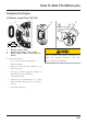


Table Of Contents
- Table of Contents
- 1 Foreword
- 2 Safety First
- 3 Warning Labels
- 4 Parts Identification
- 5 Serial Numbers
- 6 Instruments
- 6.1 Instrument Displays Overview
- 6.2 Thin Film Transistor (TFT) Instrument Display
- 6.2.1 Instrument Panel Layout
- 6.2.2 TFT Display Navigation
- 6.2.3 TFT Themes and Styles
- 6.2.4 Warning Lights
- 6.2.4.1 Engine Management System Malfunction Indicator Light (MIL)
- 6.2.4.2 Low Oil Pressure Warning Light
- 6.2.4.3 Immobiliser/Alarm Indicator Light
- 6.2.4.4 ABS (Anti-Lock Brake System) Warning Light
- 6.2.4.5 Traction Control (TC) Indicator Light
- 6.2.4.6 Traction Control (TC) Disabled Warning Light
- 6.2.4.7 Cruise Control Light
- 6.2.4.8 Triumph Semi Active Suspension (TSAS) Warning Light
- 6.2.4.9 Direction Indicators
- 6.2.4.10 Hazard Warning Lights
- 6.2.4.11 High Beam Button
- 6.2.4.12 Daytime Running Lights (DRL)
- 6.2.4.13 Low Fuel Warning Light
- 6.2.4.14 Tyre Pressure Monitoring System (TPMS) Warning Light (if fitted)
- 6.2.5 Speedometer and Odometer
- 6.2.6 Tachometer
- 6.2.7 Gear Position Display
- 6.2.8 Fuel Gauge
- 6.2.9 Service Interval Announcement
- 6.2.10 Ambient Air Temperature
- 6.2.11 Riding Modes
- 6.2.12 Riding Mode Selection
- 6.2.13 Information Tray
- 6.2.13.1 Warnings
- 6.2.13.2 Trip Meter
- 6.2.13.3 Fuel Status Information
- 6.2.13.4 Tyre Pressure Monitoring System (TPMS) (if fitted)
- 6.2.13.5 Odometer
- 6.2.13.6 Service Interval Announcement
- 6.2.13.7 Triumph Semi Active Suspension (TSAS)
- 6.2.13.8 Screen Contrast
- 6.2.13.9 Style Options
- 6.2.13.10 Coolant Temperature
- 6.2.13.11 Windscreen Adjustment
- 6.2.14 Main Menu
- 6.2.15 Instrument Panel Position Adjustment
- 6.3 Liquid Crystal Display (LCD) Instrument Display
- 6.3.1 Instrument Panel Layout
- 6.3.2 Warning Lights
- 6.3.2.1 Engine Management System Malfunction Indicator Light (MIL)
- 6.3.2.2 Low Oil Pressure Warning Light
- 6.3.2.3 High Coolant Temperature Warning Light
- 6.3.2.4 Immobiliser/Alarm Indicator Light
- 6.3.2.5 ABS (Anti-Lock Brake System) Warning Light
- 6.3.2.6 Traction Control (TC) Indicator Light
- 6.3.2.7 Traction Control (TC) Disabled Warning Light
- 6.3.2.8 Cruise Control Light
- 6.3.2.9 Direction Indicators
- 6.3.2.10 High Beam Switch
- 6.3.2.11 Fog Lights (if fitted)
- 6.3.2.12 Low Fuel Warning Light
- 6.3.2.13 Neutral
- 6.3.2.14 Battery Warning Light
- 6.3.2.15 Tyre Pressure Warning Light (if TPMS is fitted)
- 6.3.2.16 Frost Warning Light
- 6.3.3 Warning and Information Messages
- 6.3.4 Tachometer
- 6.3.5 Motorcycle Status Display Screen
- 6.3.6 Multifunction Display Screen
- 6.3.7 Settings Menu
- 6.3.8 Riding Modes
- 7 General Information
- 7.1 Hand Controls
- 7.1.1 Keyless Ignition (if fitted)
- 7.1.2 Master Ignition Switch (if fitted)
- 7.1.3 Ignition Key
- 7.1.4 Ignition Switch/Steering Lock
- 7.1.5 Right Handlebar Switches
- 7.1.6 Right Handlebar Switches
- 7.1.7 Left Handlebar Switches
- 7.1.7.1 Cruise Control Adjust Button
- 7.1.7.2 Daytime Running Lights (DRL) Switch (if fitted)
- 7.1.7.3 MODE Button
- 7.1.7.4 Direction Indicator Switch
- 7.1.7.5 Joystick Button
- 7.1.7.6 Horn Button
- 7.1.7.7 Heated Grips Switch
- 7.1.7.8 Fog Lights Switch (if fitted)
- 7.1.7.9 High Beam Button
- 7.1.7.10 Rider’s Heated Seat Switch (if fitted)
- 7.1.8 Left Handlebar Switches
- 7.1.9 Throttle Control
- 7.1.10 Brake and Clutch Lever Adjusters
- 7.2 Cruise Control
- 7.3 Triumph Semi Active Suspension (TSAS) (if fitted)
- 7.4 Traction Control (TC)
- 7.5 Tyre Pressure Monitoring System (TPMS) (if fitted)
- 7.6 Fuel
- 7.7 Windscreen
- 7.8 Handlebar Adjustment
- 7.9 Stands
- 7.10 Seats
- 7.11 Helmet Hook
- 7.12 Tool Kit, Handbook and the Triumph Accessory D-Lock
- 7.13 Electrical Accessory Sockets
- 7.14 Universal Serial Bus (USB) Socket
- 7.15 Expedition Aluminium Panniers (if fitted)
- 7.16 Running-In
- 7.17 Daily Safety Checks
- 7.1 Hand Controls
- 8 How to Ride the Motorcycle
- 9 Accessories, Loading and Passengers
- 10 Maintenance
- 10.1 Scheduled Maintenance
- 10.2 Scheduled Maintenance Table
- 10.3 Engine Oil
- 10.4 Cooling System
- 10.5 Throttle Control
- 10.6 Clutch
- 10.7 Final Drive Unit
- 10.8 Brakes
- 10.9 Steering/Wheel Bearings
- 10.10 Front Suspension
- 10.11 Rear Suspension
- 10.12 Tyres
- 10.13 Battery
- 10.14 Fuse Boxes
- 10.15 Chassis Electronic Control Module (Chassis ECM)
- 10.16 Headlights
- 10.17 Bulb Replacement
- 11 Cleaning and Storage
- 11.1 Preparation for Washing
- 11.2 Where to be Careful
- 11.3 Washing
- 11.4 After Washing
- 11.5 Care of Matt Paintwork
- 11.6 Care of Gloss Paintwork
- 11.7 Aluminium Items - not Lacquered or Painted
- 11.8 Cleaning of Chrome and Stainless Steel Items
- 11.9 Black Chrome
- 11.10 Cleaning of the Exhaust System
- 11.11 Seat Care
- 11.12 Windscreen Cleaning (if fitted)
- 11.13 Care of Leather Products
- 11.14 Preparation for Storage
- 11.15 Preparation after Storage
- 12 Specifications
- Index

How To Ride The Motorcycle
146
Starting the Engine
Tiger 1200 XR
P
U
S
H
P
O
F
F
O
N
3
5
4
RES /+
SET /-
ON
2
1
1. Engine stop switch - RUN position
2. Starter button
3. Neutral indicator light
4. ON position
5. Ignition switch
To start the engine:
• Check that the engine stop switch
is in the RUN position.
• Make sure that the transmission is
in neutral.
• Turn the ignition switch on.
Note:
• When the ignition is switched on,
the tachometer needle will quickly
sweep from zero to maximum and
then return to zero. The instrument
warning lights will illuminate and
will then go off (except those which
normally remain on until the engine
starts - see Warning Lights on
p
age
61
). It is not necessary to wait for
the needle to return to zero before
starting the engine.
• A transponder is fitted within the
key to turn off the engine
immobiliser. Only have one of the
ignition keys near the ignition
switch. Having two ignition keys
near the switch may interrupt the
signal between the transponder
and the engine immobiliser. In this
situation the engine immobiliser will
remain active until one of the
ignition keys is removed.