
User's Manual


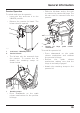


Table Of Contents
- Table of Contents
- 1 Foreword
- 2 Safety First
- 3 Warning Labels
- 4 Parts Identification
- 5 Serial Numbers
- 6 Instruments
- 6.1 Instrument Displays Overview
- 6.2 Thin Film Transistor (TFT) Instrument Display
- 6.2.1 Instrument Panel Layout
- 6.2.2 TFT Display Navigation
- 6.2.3 TFT Themes and Styles
- 6.2.4 Warning Lights
- 6.2.4.1 Engine Management System Malfunction Indicator Light (MIL)
- 6.2.4.2 Low Oil Pressure Warning Light
- 6.2.4.3 Immobiliser/Alarm Indicator Light
- 6.2.4.4 ABS (Anti-Lock Brake System) Warning Light
- 6.2.4.5 Traction Control (TC) Indicator Light
- 6.2.4.6 Traction Control (TC) Disabled Warning Light
- 6.2.4.7 Cruise Control Light
- 6.2.4.8 Triumph Semi Active Suspension (TSAS) Warning Light
- 6.2.4.9 Direction Indicators
- 6.2.4.10 Hazard Warning Lights
- 6.2.4.11 High Beam Button
- 6.2.4.12 Daytime Running Lights (DRL)
- 6.2.4.13 Low Fuel Warning Light
- 6.2.4.14 Tyre Pressure Monitoring System (TPMS) Warning Light (if fitted)
- 6.2.5 Speedometer and Odometer
- 6.2.6 Tachometer
- 6.2.7 Gear Position Display
- 6.2.8 Fuel Gauge
- 6.2.9 Service Interval Announcement
- 6.2.10 Ambient Air Temperature
- 6.2.11 Riding Modes
- 6.2.12 Riding Mode Selection
- 6.2.13 Information Tray
- 6.2.13.1 Warnings
- 6.2.13.2 Trip Meter
- 6.2.13.3 Fuel Status Information
- 6.2.13.4 Tyre Pressure Monitoring System (TPMS) (if fitted)
- 6.2.13.5 Odometer
- 6.2.13.6 Service Interval Announcement
- 6.2.13.7 Triumph Semi Active Suspension (TSAS)
- 6.2.13.8 Screen Contrast
- 6.2.13.9 Style Options
- 6.2.13.10 Coolant Temperature
- 6.2.13.11 Windscreen Adjustment
- 6.2.14 Main Menu
- 6.2.15 Instrument Panel Position Adjustment
- 6.3 Liquid Crystal Display (LCD) Instrument Display
- 6.3.1 Instrument Panel Layout
- 6.3.2 Warning Lights
- 6.3.2.1 Engine Management System Malfunction Indicator Light (MIL)
- 6.3.2.2 Low Oil Pressure Warning Light
- 6.3.2.3 High Coolant Temperature Warning Light
- 6.3.2.4 Immobiliser/Alarm Indicator Light
- 6.3.2.5 ABS (Anti-Lock Brake System) Warning Light
- 6.3.2.6 Traction Control (TC) Indicator Light
- 6.3.2.7 Traction Control (TC) Disabled Warning Light
- 6.3.2.8 Cruise Control Light
- 6.3.2.9 Direction Indicators
- 6.3.2.10 High Beam Switch
- 6.3.2.11 Fog Lights (if fitted)
- 6.3.2.12 Low Fuel Warning Light
- 6.3.2.13 Neutral
- 6.3.2.14 Battery Warning Light
- 6.3.2.15 Tyre Pressure Warning Light (if TPMS is fitted)
- 6.3.2.16 Frost Warning Light
- 6.3.3 Warning and Information Messages
- 6.3.4 Tachometer
- 6.3.5 Motorcycle Status Display Screen
- 6.3.6 Multifunction Display Screen
- 6.3.7 Settings Menu
- 6.3.8 Riding Modes
- 7 General Information
- 7.1 Hand Controls
- 7.1.1 Keyless Ignition (if fitted)
- 7.1.2 Master Ignition Switch (if fitted)
- 7.1.3 Ignition Key
- 7.1.4 Ignition Switch/Steering Lock
- 7.1.5 Right Handlebar Switches
- 7.1.6 Right Handlebar Switches
- 7.1.7 Left Handlebar Switches
- 7.1.7.1 Cruise Control Adjust Button
- 7.1.7.2 Daytime Running Lights (DRL) Switch (if fitted)
- 7.1.7.3 MODE Button
- 7.1.7.4 Direction Indicator Switch
- 7.1.7.5 Joystick Button
- 7.1.7.6 Horn Button
- 7.1.7.7 Heated Grips Switch
- 7.1.7.8 Fog Lights Switch (if fitted)
- 7.1.7.9 High Beam Button
- 7.1.7.10 Rider’s Heated Seat Switch (if fitted)
- 7.1.8 Left Handlebar Switches
- 7.1.9 Throttle Control
- 7.1.10 Brake and Clutch Lever Adjusters
- 7.2 Cruise Control
- 7.3 Triumph Semi Active Suspension (TSAS) (if fitted)
- 7.4 Traction Control (TC)
- 7.5 Tyre Pressure Monitoring System (TPMS) (if fitted)
- 7.6 Fuel
- 7.7 Windscreen
- 7.8 Handlebar Adjustment
- 7.9 Stands
- 7.10 Seats
- 7.11 Helmet Hook
- 7.12 Tool Kit, Handbook and the Triumph Accessory D-Lock
- 7.13 Electrical Accessory Sockets
- 7.14 Universal Serial Bus (USB) Socket
- 7.15 Expedition Aluminium Panniers (if fitted)
- 7.16 Running-In
- 7.17 Daily Safety Checks
- 7.1 Hand Controls
- 8 How to Ride the Motorcycle
- 9 Accessories, Loading and Passengers
- 10 Maintenance
- 10.1 Scheduled Maintenance
- 10.2 Scheduled Maintenance Table
- 10.3 Engine Oil
- 10.4 Cooling System
- 10.5 Throttle Control
- 10.6 Clutch
- 10.7 Final Drive Unit
- 10.8 Brakes
- 10.9 Steering/Wheel Bearings
- 10.10 Front Suspension
- 10.11 Rear Suspension
- 10.12 Tyres
- 10.13 Battery
- 10.14 Fuse Boxes
- 10.15 Chassis Electronic Control Module (Chassis ECM)
- 10.16 Headlights
- 10.17 Bulb Replacement
- 11 Cleaning and Storage
- 11.1 Preparation for Washing
- 11.2 Where to be Careful
- 11.3 Washing
- 11.4 After Washing
- 11.5 Care of Matt Paintwork
- 11.6 Care of Gloss Paintwork
- 11.7 Aluminium Items - not Lacquered or Painted
- 11.8 Cleaning of Chrome and Stainless Steel Items
- 11.9 Black Chrome
- 11.10 Cleaning of the Exhaust System
- 11.11 Seat Care
- 11.12 Windscreen Cleaning (if fitted)
- 11.13 Care of Leather Products
- 11.14 Preparation for Storage
- 11.15 Preparation after Storage
- 12 Specifications
- Index

General Information
131
To access the USB socket:
• Remove the passenger seat.
• Remove the cap from the USB
socket.
• Connect your device using a
suitable USB cable, then stow the
device and USB cable in the space
available under the passenger seat.
Caution
Make sure that all electronic devices
and cables are safely secured under
the seat when riding.
Make sure there is sufficient space
surrounding any electronic devices for
the seat to close without causing any
damage to the electronic device or the
motorcycle.
• Fit the passenger seat, making sure
that the device or USB cable is not
trapped.
• Turn the ignition on and start the
engine.
Caution
Do not leave the ignition switch in the
ON position unless the engine is
running as this will discharge the
battery.
• When your device has finished
charging, remove the passenger
seat and disconnect the device.
• Refit the USB socket cap and refit
the passenger seat.
Note:
• The USB socket is protected by a
chassis ECM, which will
automatically cut power to the
socket in the event of an overload.
• Power can be restored to the USB
socket by turning the ignition
switch off then on again, provided
that the socket is not still
overloaded.