
User's Manual


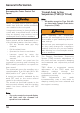
Table Of Contents
- Table of Contents
- 1 Foreword
- 2 Safety First
- 3 Warning Labels
- 4 Parts Identification
- 5 Serial Numbers
- 6 Instruments
- 6.1 Instrument Displays Overview
- 6.2 Thin Film Transistor (TFT) Instrument Display
- 6.2.1 Instrument Panel Layout
- 6.2.2 TFT Display Navigation
- 6.2.3 TFT Themes and Styles
- 6.2.4 Warning Lights
- 6.2.4.1 Engine Management System Malfunction Indicator Light (MIL)
- 6.2.4.2 Low Oil Pressure Warning Light
- 6.2.4.3 Immobiliser/Alarm Indicator Light
- 6.2.4.4 ABS (Anti-Lock Brake System) Warning Light
- 6.2.4.5 Traction Control (TC) Indicator Light
- 6.2.4.6 Traction Control (TC) Disabled Warning Light
- 6.2.4.7 Cruise Control Light
- 6.2.4.8 Triumph Semi Active Suspension (TSAS) Warning Light
- 6.2.4.9 Direction Indicators
- 6.2.4.10 Hazard Warning Lights
- 6.2.4.11 High Beam Button
- 6.2.4.12 Daytime Running Lights (DRL)
- 6.2.4.13 Low Fuel Warning Light
- 6.2.4.14 Tyre Pressure Monitoring System (TPMS) Warning Light (if fitted)
- 6.2.5 Speedometer and Odometer
- 6.2.6 Tachometer
- 6.2.7 Gear Position Display
- 6.2.8 Fuel Gauge
- 6.2.9 Service Interval Announcement
- 6.2.10 Ambient Air Temperature
- 6.2.11 Riding Modes
- 6.2.12 Riding Mode Selection
- 6.2.13 Information Tray
- 6.2.13.1 Warnings
- 6.2.13.2 Trip Meter
- 6.2.13.3 Fuel Status Information
- 6.2.13.4 Tyre Pressure Monitoring System (TPMS) (if fitted)
- 6.2.13.5 Odometer
- 6.2.13.6 Service Interval Announcement
- 6.2.13.7 Triumph Semi Active Suspension (TSAS)
- 6.2.13.8 Screen Contrast
- 6.2.13.9 Style Options
- 6.2.13.10 Coolant Temperature
- 6.2.13.11 Windscreen Adjustment
- 6.2.14 Main Menu
- 6.2.15 Instrument Panel Position Adjustment
- 6.3 Liquid Crystal Display (LCD) Instrument Display
- 6.3.1 Instrument Panel Layout
- 6.3.2 Warning Lights
- 6.3.2.1 Engine Management System Malfunction Indicator Light (MIL)
- 6.3.2.2 Low Oil Pressure Warning Light
- 6.3.2.3 High Coolant Temperature Warning Light
- 6.3.2.4 Immobiliser/Alarm Indicator Light
- 6.3.2.5 ABS (Anti-Lock Brake System) Warning Light
- 6.3.2.6 Traction Control (TC) Indicator Light
- 6.3.2.7 Traction Control (TC) Disabled Warning Light
- 6.3.2.8 Cruise Control Light
- 6.3.2.9 Direction Indicators
- 6.3.2.10 High Beam Switch
- 6.3.2.11 Fog Lights (if fitted)
- 6.3.2.12 Low Fuel Warning Light
- 6.3.2.13 Neutral
- 6.3.2.14 Battery Warning Light
- 6.3.2.15 Tyre Pressure Warning Light (if TPMS is fitted)
- 6.3.2.16 Frost Warning Light
- 6.3.3 Warning and Information Messages
- 6.3.4 Tachometer
- 6.3.5 Motorcycle Status Display Screen
- 6.3.6 Multifunction Display Screen
- 6.3.7 Settings Menu
- 6.3.8 Riding Modes
- 7 General Information
- 7.1 Hand Controls
- 7.1.1 Keyless Ignition (if fitted)
- 7.1.2 Master Ignition Switch (if fitted)
- 7.1.3 Ignition Key
- 7.1.4 Ignition Switch/Steering Lock
- 7.1.5 Right Handlebar Switches
- 7.1.6 Right Handlebar Switches
- 7.1.7 Left Handlebar Switches
- 7.1.7.1 Cruise Control Adjust Button
- 7.1.7.2 Daytime Running Lights (DRL) Switch (if fitted)
- 7.1.7.3 MODE Button
- 7.1.7.4 Direction Indicator Switch
- 7.1.7.5 Joystick Button
- 7.1.7.6 Horn Button
- 7.1.7.7 Heated Grips Switch
- 7.1.7.8 Fog Lights Switch (if fitted)
- 7.1.7.9 High Beam Button
- 7.1.7.10 Rider’s Heated Seat Switch (if fitted)
- 7.1.8 Left Handlebar Switches
- 7.1.9 Throttle Control
- 7.1.10 Brake and Clutch Lever Adjusters
- 7.2 Cruise Control
- 7.3 Triumph Semi Active Suspension (TSAS) (if fitted)
- 7.4 Traction Control (TC)
- 7.5 Tyre Pressure Monitoring System (TPMS) (if fitted)
- 7.6 Fuel
- 7.7 Windscreen
- 7.8 Handlebar Adjustment
- 7.9 Stands
- 7.10 Seats
- 7.11 Helmet Hook
- 7.12 Tool Kit, Handbook and the Triumph Accessory D-Lock
- 7.13 Electrical Accessory Sockets
- 7.14 Universal Serial Bus (USB) Socket
- 7.15 Expedition Aluminium Panniers (if fitted)
- 7.16 Running-In
- 7.17 Daily Safety Checks
- 7.1 Hand Controls
- 8 How to Ride the Motorcycle
- 9 Accessories, Loading and Passengers
- 10 Maintenance
- 10.1 Scheduled Maintenance
- 10.2 Scheduled Maintenance Table
- 10.3 Engine Oil
- 10.4 Cooling System
- 10.5 Throttle Control
- 10.6 Clutch
- 10.7 Final Drive Unit
- 10.8 Brakes
- 10.9 Steering/Wheel Bearings
- 10.10 Front Suspension
- 10.11 Rear Suspension
- 10.12 Tyres
- 10.13 Battery
- 10.14 Fuse Boxes
- 10.15 Chassis Electronic Control Module (Chassis ECM)
- 10.16 Headlights
- 10.17 Bulb Replacement
- 11 Cleaning and Storage
- 11.1 Preparation for Washing
- 11.2 Where to be Careful
- 11.3 Washing
- 11.4 After Washing
- 11.5 Care of Matt Paintwork
- 11.6 Care of Gloss Paintwork
- 11.7 Aluminium Items - not Lacquered or Painted
- 11.8 Cleaning of Chrome and Stainless Steel Items
- 11.9 Black Chrome
- 11.10 Cleaning of the Exhaust System
- 11.11 Seat Care
- 11.12 Windscreen Cleaning (if fitted)
- 11.13 Care of Leather Products
- 11.14 Preparation for Storage
- 11.15 Preparation after Storage
- 12 Specifications
- Index

General Information
106
Brake Use
Warning
Reduce speed and do not continue to
ride for longer than is necessary with
the malfunction indicator light
illuminated. The fault may adversely
affect engine performance, exhaust
emissions and fuel consumption.
Reduced engine performance could
cause a dangerous riding condition,
leading to loss of motorcycle control
and an accident.
Contact an authorised Triumph dealer
as soon as possible to have the fault
checked and rectified.
At low throttle opening (approximately
20°), the brakes and throttle can be
used together.
At high throttle opening (greater than
20°), if the brakes are applied for more
than two seconds the throttles will close
and the engine speed will reduce. To
return to normal throttle operation,
release the throttle control, release the
brakes and then re-open the throttle.
Brake and Clutch Lever Adjusters
Warning
Do not attempt to adjust the lever with
the motorcycle in motion as this may
lead to loss of motorcycle control and
an accident.
Warning
Continued
After adjusting the lever, operate the
motorcycle in an area free from traffic
to gain familiarity with the new lever
setting. Do not loan your motorcycle to
anyone as they may change the lever
setting from the one you are familiar
with causing loss of motorcycle control
and an accident.
2
1
chdd_2
1. Adjuster wheel, brake lever shown
2. Arrow mark
An adjuster is fitted to both the front
brake and clutch levers. The adjusters
allow the distance from the handlebar
to the lever to be changed to one of five
positions for the front brake lever or
four positions for the clutch lever, to
suit the span of the operator's hands.
To adjust the lever:
• Push the lever forward and turn
the adjuster wheel to align one of
the numbered positions with the
arrow mark on the lever holder.
• The distance from the handlebar
grip to the released lever is
shortest when set to number five,
and longest when set to number
one.