
User's Manual

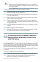
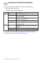
Table Of Contents
- QSG_571_EN-ok
- Where to Go From Here
- Before You Begin
- Cisco WAP571 Wireless-AC/N Premium Dual Radio Access Point with PoE Setup Features
- Mounting the Cisco WAP571 Wireless-AC/ N Premium Dual Radio Access Point with PoE Setup
- Connecting the Cisco WAP571 Wireless- AC/N Premium Dual Radio Access Point with PoE Setup
- Verifying the Hardware Installation
- Getting Started with the Configuration
- Suggested Next Steps
- Rebooting the Devices or Returning them to their Factory Default Settings
- WAP571_ClassB_RCSI (For FCC only)_20150819-ok
- Translated Safety Warnings
- Statement 1071—Warning Definition
- Statement 1—Power Disconnection Warning
- Statement 248—Unit Mounting Warning
- Statement 1004—Installation Instructions
- Statement 1005—Circuit Breaker
- Statement 1040—Product Disposal
- Statement 1044—Port Connections
- Statement 1072—Shock Hazard from Interconnections
- Statement 1073—No User-Serviceable Parts
- Statement 1074—Comply with Local and National Electrical Codes
- Product Usage Restrictions
- Declaration of Conformity Statements
- European Directives
- EU Battery Disposal and Recycling
- Standards Compliance
- EMC Class B Notices and Warnings
- Japanese Electric Appliance and Radio Laws
- Radio
- Generic Discussion on RF Exposure
- Obtaining Documentation and Submitting a Service Request
- Translated Safety Warnings

5 Cisco WAP571 Wireless Access Point
N
OTE WAP571 bundles the two Ethernet ports to be link
aggregation mode. If the two Ethernet ports have been connected
at the same time, the link partner must also support link
aggregation.
After installation, all lights should be active. Refer to Verifying the
Hardware Installation, page 6 for details about the different lights on each
switch.