
User's Manual

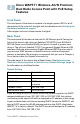
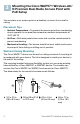
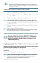
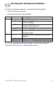
Table Of Contents
- QSG_571_EN-ok
- Where to Go From Here
- Before You Begin
- Cisco WAP571 Wireless-AC/N Premium Dual Radio Access Point with PoE Setup Features
- Mounting the Cisco WAP571 Wireless-AC/ N Premium Dual Radio Access Point with PoE Setup
- Connecting the Cisco WAP571 Wireless- AC/N Premium Dual Radio Access Point with PoE Setup
- Verifying the Hardware Installation
- Getting Started with the Configuration
- Suggested Next Steps
- Rebooting the Devices or Returning them to their Factory Default Settings
- WAP571_ClassB_RCSI (For FCC only)_20150819-ok
- Translated Safety Warnings
- Statement 1071—Warning Definition
- Statement 1—Power Disconnection Warning
- Statement 248—Unit Mounting Warning
- Statement 1004—Installation Instructions
- Statement 1005—Circuit Breaker
- Statement 1040—Product Disposal
- Statement 1044—Port Connections
- Statement 1072—Shock Hazard from Interconnections
- Statement 1073—No User-Serviceable Parts
- Statement 1074—Comply with Local and National Electrical Codes
- Product Usage Restrictions
- Declaration of Conformity Statements
- European Directives
- EU Battery Disposal and Recycling
- Standards Compliance
- EMC Class B Notices and Warnings
- Japanese Electric Appliance and Radio Laws
- Radio
- Generic Discussion on RF Exposure
- Obtaining Documentation and Submitting a Service Request
- Translated Safety Warnings

Cisco WAP571 Wireless Access Point 4
WARNING Insecure mounting might damage the device or cause injury.
Cisco is not responsible for damages incurred by insecure wall
or ceiling mounting.
To mount the Cisco WAP 571 device to a wall or ceiling:
STEP 1 Determine where you want to mount the device. Verify that the
surface is smooth, flat, dry, and sturdy.
STEP 2 Drill two pilot holes into the surface 2.75 inches (70 mm) apart for
your Cisco WAP device.
STEP 3 Insert a screw into each hole, leaving a gap between the surface
and the base of the screw head.
STEP 4 Place the upper slots of the bracket over the screws, adjust the
screws accordingly, and slide the bracket down until the screws fit
snugly into the slots.
STEP 5 Using the bracket as a template, drill two more holes for the lower
screws.
STEP 6 Insert a screw into each lower hole.
STEP 7 Slide the WAP device into the bracket, placing the cable through
the break-out tab found in the back of the bracket.
Connecting the Cisco WAP571 Wireless-
AC/N Premium Dual Radio Access Point
with PoE Setup
The WiFi default SSID is “Cisco SB-Setup” with the passphrase “cisco123”
in WPA2-PSK AES. This wireless default configuration will not allow traffic
between WiFi and Ethernet; users will need to go through the setup wizard
to resume the traffic between WiFi and Ethernet.
The user can also perform the initial configuration using a wired Ethernet
connection.
To connect the device to the wired network:
STEP 1 Connect the Ethernet cable to the Ethernet port of a PoE switch.
STEP 2 Connect the other end of the network Ethernet cable to the
Ethernet port (PoE) of the wireless access point.
4