
User's Manual

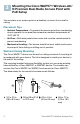
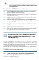

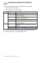
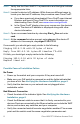
Table Of Contents
- QSG_571_EN-ok
- Where to Go From Here
- Before You Begin
- Cisco WAP571 Wireless-AC/N Premium Dual Radio Access Point with PoE Setup Features
- Mounting the Cisco WAP571 Wireless-AC/ N Premium Dual Radio Access Point with PoE Setup
- Connecting the Cisco WAP571 Wireless- AC/N Premium Dual Radio Access Point with PoE Setup
- Verifying the Hardware Installation
- Getting Started with the Configuration
- Suggested Next Steps
- Rebooting the Devices or Returning them to their Factory Default Settings
- WAP571_ClassB_RCSI (For FCC only)_20150819-ok
- Translated Safety Warnings
- Statement 1071—Warning Definition
- Statement 1—Power Disconnection Warning
- Statement 248—Unit Mounting Warning
- Statement 1004—Installation Instructions
- Statement 1005—Circuit Breaker
- Statement 1040—Product Disposal
- Statement 1044—Port Connections
- Statement 1072—Shock Hazard from Interconnections
- Statement 1073—No User-Serviceable Parts
- Statement 1074—Comply with Local and National Electrical Codes
- Product Usage Restrictions
- Declaration of Conformity Statements
- European Directives
- EU Battery Disposal and Recycling
- Standards Compliance
- EMC Class B Notices and Warnings
- Japanese Electric Appliance and Radio Laws
- Radio
- Generic Discussion on RF Exposure
- Obtaining Documentation and Submitting a Service Request
- Translated Safety Warnings

9 Cisco WAP571 Wireless Access Point
STEP 1 Verify that the Cisco WAP571 is powered on and the lights indicate
the appropriate links.
STEP 2 Locate the device’s IP address. While there are different ways to
locate your device’s IP address, this procedure uses Cisco FindIT.
a. If you have previously downloaded Cisco FindIT, open Internet
Explorer and launch Cisco FindIT. For more information on
downloading Cisco FindIT, see www.cisco.com/go/findit.
b. In the Cisco FindIT display, place your mouse over the device’s
name. The device IP address is displayed along with other
device information.
STEP 3 Open a command window by choosing Start > Run and enter
cmd.
STEP 4 At the command window prompt, enter ping and the device IP
address. In this example, we pinged 192.0.2.10.
If successful, you should get a reply similar to the following:
Pinging 192.0.2.10 with 32 bytes of data:
Reply from 192.0.2.10: bytes=32 time<1ms TTL=128
If it fails, you should get a reply similar to the following:
Pinging 192.0.2.10 with 32 bytes of data:
Request timed out.
Possible Cause of Installation Failure
No Power
• Power up the switch and your computer if they are turned off.
• Make sure your PoE switch is powered on and the lights indicate that
you have a link. See Verifying the Hardware Installation, page 6.
• Verify that the devices on your network are not plugged into a
switchable outlet.
Bad Ethernet Connection
• Check the state of the indicator lights. See Verifying the Hardware
Installation, page 6.
• Check the Ethernet cable to ensure that it is firmly connected to your
devices. Devices connected by the Ethernet cable can include the WAP
device, and routers, any switches, and your computer.
• Verify the connected switch has auto-negotiation enabled. The access
point and the switch need the same negotiation parameters set.