
User's Manual
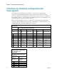

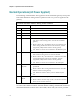
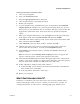
Table Of Contents
- Notice à l’attention des installateurs de réseaux câblés
- Mitteilung für CATV-Techniker
- Aviso a los instaladores de sistemas CATV
- IMPORTANT SAFETY INSTRUCTIONS
- Power Source Warning
- Ground the Product
- Protect the Product from Lightning
- Verify the Power Source from the On/Off Power Light
- Eliminate AC Power/Mains Overloads
- Provide Ventilation and Select a Location
- Operating Environment
- Protect from Exposure to Moisture and Foreign Objects
- Service Warnings
- Check Product Safety
- Protect the Product When Moving It
- United States FCC Compliance
- Introducing the DOCSIS Wireless Residential Gateway
- Purpose
- Installing the DOCSIS Wireless Residential Gateway
- Introduction
- Operation of Front Panel Indicators
- Introduction
- Troubleshooting the DOCSIS Wireless Residential Gateway
- Frequently Asked Questions
- How Do I Configure TCP/IP Protocol?
- How Do I Renew the IP Address on My PC?
- What if I Don't Subscribe to Cable TV?
- How Do I Arrange for Installation?
- How Does the Wireless Residential Gateway Connect to My Computer?
- After My Wireless Residential Gateway Is Connected, How Do I Access the Internet?
- Can I Watch TV and Surf the Internet at the Same Time?
- Common Troubleshooting Issues
- Tips for Improved Performance
- Frequently Asked Questions
- Introduction
- Customer Information
- Introduction
- Index

Chapter 3 Operation of Front Panel Indicators
17
OL-30545-01
Initial Power Up, Calibration, and Registration (AC
Power Applied)
The following chart illustrates the sequence of steps and the corresponding
appearance of the residential gateway front panel LED status indicators during
power up, calibration, and registration on the network when AC power is applied to
the residential gateway. Use this chart to troubleshoot the power up, calibration, and
registration process of your residential gateway.
Note: After the residential gateway completes Step 7 (Data Network Registration
Complete), the residential gateway proceeds immediately to Normal Operations. See
Normal Operations (AC Power Applied) (on page 20).
Front Panel LED Status Indicators During Initial Power Up, Calibration, and
Registration
Part 1, High Speed Data Registration
Step: 1 2 3 4 5 6
Front Panel
Indicator
Self
Test
Downstream
Scan
Downstream
Signal Lock
Ranging
Requesting IP
Address
Request High Speed
Data Provisioning
File
1
POWER
On
On
On
On
On
On
2
DS
On
Blinking
On
On
On
On
3
US
On
Off
Off
Blinking
On
On
4
ONLINE
On
Off
Off
Off
Off
Blinking
5
LINK
On
Off, On, or
Blinking
Off, On, or
Blinking
Off, On, or
Blinking
Off, On, or
Blinking
Off, On, or Blinking
6
USB
On
Off, On, or
Blinking
On or Blinking
On or
Blinking
On or Blinking
On or Blinking
7
WIRELESS
ON/OFF
Off
On or Blinking
On or Blinking
On or
Blinking
On or Blinking
On or Blinking
8
WIRELESS
SETUP
Off
On or Blinking
On or Blinking
On or
Blinking
On or Blinking
On or Blinking
Front Panel LED Status
Indicators During Initial Power
Up, Calibration, and
Registration
High Speed Data Registration
(continued)
Step: 7
Front Panel
Indicator
Data Network
Registration
Complete
1
POWER
On
2
DS
On
3
US
On
4
ONLINE
On
5
LINK
On