
User's Manual
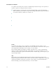
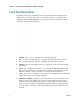

Table Of Contents
- Notice à l’attention des installateurs de réseaux câblés
- Mitteilung für CATV-Techniker
- Aviso a los instaladores de sistemas CATV
- IMPORTANT SAFETY INSTRUCTIONS
- Power Source Warning
- Ground the Product
- Protect the Product from Lightning
- Verify the Power Source from the On/Off Power Light
- Eliminate AC Power/Mains Overloads
- Provide Ventilation and Select a Location
- Operating Environment
- Protect from Exposure to Moisture and Foreign Objects
- Service Warnings
- Check Product Safety
- Protect the Product When Moving It
- United States FCC Compliance
- Introducing the DOCSIS Wireless Residential Gateway
- Purpose
- Installing the DOCSIS Wireless Residential Gateway
- Introduction
- Operation of Front Panel Indicators
- Introduction
- Troubleshooting the DOCSIS Wireless Residential Gateway
- Frequently Asked Questions
- How Do I Configure TCP/IP Protocol?
- How Do I Renew the IP Address on My PC?
- What if I Don't Subscribe to Cable TV?
- How Do I Arrange for Installation?
- How Does the Wireless Residential Gateway Connect to My Computer?
- After My Wireless Residential Gateway Is Connected, How Do I Access the Internet?
- Can I Watch TV and Surf the Internet at the Same Time?
- Common Troubleshooting Issues
- Tips for Improved Performance
- Frequently Asked Questions
- Introduction
- Customer Information
- Introduction
- Index

Chapter 1 Introducing the DOCSIS Wireless Residential Gateway
4 OL-30545-01
Front Panel Description
The front panel of your residential gateway provides LED status indicators that
indicate how well and at what state your residential gateway is operating. See
Operation of Front Panel Indicators (on page 17), for more information on front
panel LED status indicator functions.
1 POWER—ON, power is applied to the residential gateway.
2 DS—ON, the residential gateway is receiving data from the cable network.
3 US—ON, the residential gateway is sending data to the cable network.
4 ONLINE—ON, the residential gateway is registered on the network and fully
operational.
5 LINK—ON, the Ethernet connection is operational. BLINKING indicates that
data is being transferred over the Ethernet connection. OFF indicates that the
Ethernet connection is not connected or has been disabled by the user.
6 USB—ON, a device is connected to the USB port. BLINKING indicates that data
is being transferred over the USB connection.
7 WIRELESS ON/OFF (Optional)—Press this button to activate and turn on the
Wireless feature. This feature allows users to transfer data over the wireless
connection. When the WIRELESS indicator is ON, it indicates that the Wireless
Access Point is operational. BLINKING indicates that data is being transferred
over the wireless connection. OFF indicates that the Wireless feature has been
disabled.