
Specifications


8 of 42
ISSUED: 02-15-10 SHEET #: 095-9316-2 08-02-11
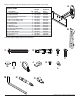
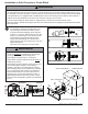
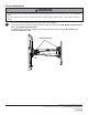
Mounting and Removing Flat Panel Display
Hook adapter brackets (B) onto adapter plate (A).
Turn security screws, using phillips screwdriver,
clockwise at least six times to prevent display from
being removed as shown in cross section of fi g.
3.1.
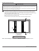
NOTE: To lock the display down, tighten safety/
security screws to wall plate as shown in cross
section.
To remove display from mount, loosen safety/
security screws, swing display away from mount,
and lift display off of mount.
3
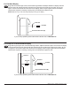
• Always use an assistant or mechanical lifting equipment to safely lift and position the fl at panel displays.
WARNING
B
• Do not tighten screws with excessive force.
Overtightening can cause damage to mount. Tighten
screws to 40 in. • lb (4.5 N.M.) maximum torque.
CAUTION
fi g 3.1
A
SECURITY
SCREWS
B
A
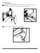
• If screws become loose over time, tighten screws
as necessary. Tighten screws to 50 in • lbs
(5.6 N.M.) maximum torque.
WARNING
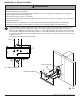
DETAIL 1
If more or less tension is desired in tilt mechanism,
remove snap caps as shown in detail 1. Insert
a fl at head screwdriver into slot and pry cap
away from tilt mechanism. To adjust tilt, tighten
or loosen socket screw no more than half a turn
using 5 mm allen wrench (M).
To adjust roll (5° left or right), tighten or loosen
10-32 x 1/2" phillips screw.
4
SOCKET
SCREW
SNAP
CAP
SLOT
10-32 X 1/2"
SCREW
CROSS SECTION