
Instruction Manual


C. Support Kit Installation for Grid Ceilings (F1)
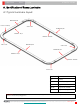
IMPORTANT: CONTRACTOR TO RUN MIN. 12GA WIRE THROUGH CODE-COMPLIANT METAL CONDUIT, MAX. 50. FT
© 2014 Acuity Brands Lighting, Inc. All Rights Reserved.. Products in this document may be covered by one or more U.S. Patents and Patents Pending. Specifications subject to change without
notice. Limited warranty applies. Complete warranty terms located at www.AcuityBrands.com/CustomerResources/Terms_and_Conditions.aspx
PEERLESS RENNA
7
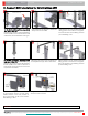
For On-Grid Installations follow steps C1-C3
then skip to Step C7: In an accompanying
hardware box, locate a Universal Mounting
Bracket (UMB). Insert bolt into bottom hole
of Bracket A, then hook Bracket A onto grid.
Hook Bracket B onto Bracket A. Letters are
clearly marked on the UMB.
Adjust brackets to proper location along the
ceiling grid then screw sides A to B together.
Secure the brackets to the building structure
per local building codes.
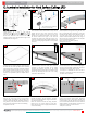
For Off-Grid Installations, skip steps C1-C3
begin here at Step C4: In an accompanying
hardware box, locate a Universal Mounting
Bracket (UMB). Insert bolt into Bracket A.
Hook Bracket B onto Bracket A. Secure with
nut (DO NOT TIGHTEN).
Slide hanger (by others) onto Caddy Bar and
fit Caddy Bar into upper slots in the bracket.
Adjust brackets to proper location along the
ceiling grid then screw sides A to B together.
Secure the brackets to the building structure
per local building codes.
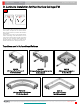
Hang J-box assembly onto Bracket A tab
and screw J-box to bracket.
Locate the matching driver enclosure box
for the luminaire section currently being
installed. Remove cover from provided J-
box by unscrewing 2X #8 screws. Attach
black bushing to J-Box.
Bend tabs straight if grid interferes
with UMB placements
Structure
wires
Black bushing
09/26 ECO#074-293246
PIN007904 REV. E