
PureFire PFA-1 Interface Adaptor Installation, Operation, and Maintenance Manual


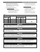


2. Analog Input of Rate:
Input voltage below 2 volts dc will disable boiler
operation. 2 volts corresponds to minimum boiler
input which will display as 1% Input on the RC
Display (see boiler manual for minimum input
ratings). 10 volts corresponds to maximum boiler
input, and voltages in between will linearly adjust the
input rate.
G. OPERATION – MODBUS INTERFACE
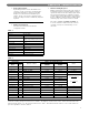
1. Modbus Configuration:
The table below summarizes the Modbus
configuration details:
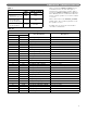
2. Modbus Holding Registers:
Modbus communicates using “words” (the contents of
16 bit holding registers). The PFA-1 Interface Adapter
organizes the data in read-only holding registers. Table
2 shows the information that is available for reading
and the address of the holding registers. Depending on
the type of Modbus software used, the holding register
addressing range starts at either 0x0000 or 0x0001.
The values of STATE and ERROR_NUMBER can
be used to determine whether the boiler control is
operating correctly, not communicating or in an
error state.
PUREFIRE PFA-1 INTERFACE ADAPTER
Table 2
Table 1
Modbus Configuration Specifications
Protocol Modbus RTU
Default Address 0x01 (settable with SiteVision)
Supported Commands
• Read Holding Registers (0x03)*
• Write single holding register (0x06)
Baud Rate 9600 bps
Data Length 8 bits
Parity None
Stop Bits 1
Physical Layer RS485 (2 wire)
Modbus 1 A Connection J7-1
Modbus 1 B Connection J7-3
Buffer Size
8 registers per frame
Modbus Holding Registers (Read Only)
Item Index
Parameter Name
Address & Holding Registers
Notes
Word byte
Range Start
0x0000
Range Start
0x0001
0 High byte 0 STATE 0x0000 0x0001 See Table 3
0 Low byte 1 STATUS 0x0000 0x0001 See Table 4
2 High byte 2 ERROR_NUMBER 0x0002 0x0003 See Table 6
2 Low byte 3 WARNING_NUMBER 0x0002 0x0003 See Table 7
4 High byte 4 FLOW_TEMP* 0x0004 0x0005
°C=byte value
2
–10
°F=°Cx9
5
+32
4 Low byte 5 RETURN_TEMP 0x0004 0x0005
6 High byte 6 DHW_TEMP 0x0006 0x0007
6 Low byte 7 FLUE_TEMP 0x0006 0x0007
8 High byte 8 NOT USED 0x0008 0x0009
8 Low byte 9 NOT USED 0x0008 0x0009
10 High byte 10 APPLIANCE_TYPE 0x000A 0x000B
—
10 Low byte 11 CONTROL_CONFIG_BYTE 0x000A 0x000B
—
12 High byte 12 CH_MODE 0x000C 0x000D
—
12 Low byte 13 DHW_MODE 0x000C 0x000D
—
14 High byte 14 CH_SETPOINT 0x000E 0x000F
—
14 Low byte 15 DHW_SETPOINT 0x000E 0x000F
—
* FLOW_TEMP is the boiler supply (outlet) water temperature.
To read these values, issue a Modbus command to read a holding register. For example, if a command is issued to read
0x0000 the resulting, unsigned word may read, “0x090F”. The high byte for this word is “0x09”. Table 3 shows that this value
indicates that the burner is on. The low byte for this word is “0x0F”. This indicates that the boiler is on as a result of the freeze
protection algorithm as shown in Table 4.
3