
PureFire PFA-1 Interface Adaptor Installation, Operation, and Maintenance Manual


D. ELECTRICAL – WIRING
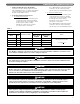
1. Figure 3 shows customer wiring connections for the
PFA-1 Interface Board.
2. PF-210 & PF-399 boilers are equipped with harnesses
that provide power and communication to the
Interface Board, and alarm contact output to the boiler
terminal strip. Connect alarm to boiler terminal strip.
3. Analog Input (where used):
a. For the PF-210 and PF-399, connect the analog
input device to terminals #15 (+) and #16 (-)
on the boiler terminal strip located behind the
remote control display.
b. For the PF-50, PF-80, PF-110, and PF-140
boilers, connect the analog input device to the
red wires from the J5 connector of the Interface
Adapter. Be sure that these wires are connected
with the proper polarity.
E. OPERATION – ALARM CONTACTS
Alarm Output:
a. The alarm output is a normally open dry contact.
If an error is sensed in one of the attached
boilers, the Alarm Output contact closes.
b. This output can be used with either line voltage
or 24 volts to power a lamp, buzzer, phone dialer
or building management system.
F. OPERATION – ANALOG INPUT
For external control of setpoint temperature or input rate
of a P
UREFIRE Boiler, a 2-10 volt dc analog signal is to
be applied as shown in Figure 3 to the analog input
wires.
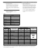
1. Analog Input at Setpoint:
Input voltage below 2 volts dc will disable boiler
operation. 2 volts corresponds to a boiler setpoint
temperature of 60°F and 10 volts corresponds to a
boiler setpoint temperature of 200°F. Input voltage
between 2 and 10 volts will result in a boiler setpoint
temperature proportional to the difference between
the 2 volt temperature and the 10 volt temperature.
For example, an input of 6 volts will result in a boiler
setpoint temperature of 130°F.
PUREFIRE PFA-1 INTERFACE ADAPTER
Figure 3: Electrical Wiring
If the analog input is not connected and there is no
connection between the red and red/white Analog
Input wires, the default input voltage is 2.5 Vdc.
Therefore, the boiler will likely run without an analog
input signal. In this case, all of the standard limits
and safety switches will continue to function properly.
NOTICE
2