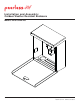
Installation and Assembly: Outdoor Weather Resistant Enclosure Models: HDS-OWRE-200 2300 White Oak Circle • Aurora, Il 60502 • (800) 865-2112 • Fax: (800) 359-6500 • www.peerless-av.
Note: Read entire instruction sheet before you start installation and assembly. WARNING • Do not begin to install your Peerless product until you have read and understood the instructions and warnings contained in this Installation Sheet. If you have any questions regarding any of the instructions or warnings, for US customers please call Peerless customer care at 1-800-865-2112, for all international customers, please contact your local distributor.
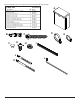
Before you begin, make sure all parts shown are included with your product. Parts List A B C D E F G H I J K L Description wireless receiver enclosure, outdoor concrete anchor #14 x 2.5" wood screw cable tie .187 x 7.5 lg. cable tie .04 x 5.75 lg. push-in round plastic plug, 3/8" 1/4-20 x 1/2 socket head screw lock nut 1/4-20 cable management sheath enclosure mounting bracket, small enclosure mounting bracket, large 4 mm allen wrench Qty.
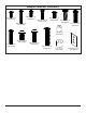
Adapter Bracket Fasteners M4 x 12 mm (6) (510-D1079) M5 x 12 mm (4) (520-D1064) M5 x 25 mm (4) (520-D1122) M4 x 25 mm (4) (510-D1082) M6 x 12 mm (4) (520-D1050) M6 x 20 mm (4) (520-D1554) M6 x 25 mm (4) (520-D1211) I.D. .22" (4) (540-1057) M8 x 12 mm (6) (520-D1068) M6 x 30 mm (4) (520-D1067) M8 x 25 mm (4) (520-D1101) M8 x 40 mm (4) (520-D1152) 4 of 22 I.D. .
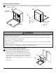
Enclosure Wall Installation 1 Open the wireless receiver enclosure (A) and remove the sub panel assembly as shown in fig. 1.1. Choose two holes for securing the wireless receiver enclosure (A). Press in plastic plug (F) into the four remaining holes shown in figure 1.2. A A SUB PANEL ASSEMBLY F MOUNTING HOLES fig. 1.1 fig. 1.2 WARNING • Installer must verify that the supporting surface will safely support the combined load of the equipment and all attached hardware and components.
Enclosure Wall Installation to Solid Concrete or Cinder Block WARNING • Verify that you have a minimum of 1-3/8" (35mm) of actual concrete thickness in the hole to be used for the concrete anchors. Do not drill into mortar joints! Be sure to mount in a solid part of the block, generally 1" (25mm) minimum from the side of the block. Cinder block must meet ASTM C-90 specifications.
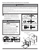
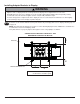
Enclosure Installation to ESA763PU Articulating Wall Mount NOTE: If display has a VESA 400 horizontal mounting pattern, skip to step 4 on page 8. NOTE: For VESA 200x200 or VESA 200x100 mount hole patterns, skip to step 6 on page 11. 3 1/4-20 x 1.25" SCREWS Remove four 1/4-20 x .6" screws using a 5 mm allen wrench and loosen two 1/4-20 x 1.25" screws 1/2 turn to allow for display bracket adjustment. 1/4-20 x .
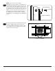
Open the wireless receiver enclosure (A) and remove the sub panel assembly as shown in fig. 4.1. Loosely attach the small enclosure mounting brackets (J) to the wireless receiver enclosure (A) with two 1/4-20 x 1/2 socket head screws (G) and two 1/4-20 nuts (H) as shown in fig. 4.2. NOTE: The enclosure mounting bracket can be installed with the inside notch facing downward if additional side-to-side adjustment is needed.
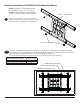
Installing Adapter Brackets to Display WARNING • Tighten screws so display brackets are firmly attached to display. Do not tighten with excessive force. Overtightening can cause stress damage to screws, greatly reducing their holding power and possibly causing screw heads to become detached. Tighten to 40 in. • lb (4.5 N.M.) maximum torque.
NOTE: enclosure removed for clarity. 5-2 Begin with the longest length screw, hand thread screw through multi-washer, display brackets and spacer in that order into display as shown below. Screw must make at least three full turns into the mounting hole and fit snug into place. Do not over tighten. If screw cannot make three full turns into the display, select a shorter length screw from the baffled fastener pack. Repeat for remaining mounting holes, level display brackets and tighten screws.
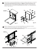
Enclosure Installation to ESA763PU Articulating Wall Mount VESA 200 x 200 or VESA 200 x 100 Mounting Pattern Remove four 1/4-20 x .6" screws using a 5mm allen wrench and loosen two 1/4-20 x 1.25" screws 1/2 turn to allow for display bracket adjustment. 6 1/4-20 x 1.25" SCREWS 1/4-20 x .6" SCREWS 6-1 Remove four 1/4-20 self tapping screws to detach display brackets from outer mount holes of the universal adapter bracket using a 5mm allen wrench as shown in figure 6.1.
6-2 Open the wireless receiver enclosure (A) and remove the sub panel assembly as shown in fig. 6.3. Loosely attach the large enclosure mounting brackets (K) to the wireless receiver enclosure (A) with two 1/4-20 x 1/2 socket head screws (G) and two 1/4-20 nuts (H) as shown in fig. 6.4. NOTE: The enclosure mounting bracket can be installed with the inside notch facing downward if additional side-to-side adjustment is needed.
6-4 Align one display bracket with one set of display mounting holes. Place spacers between display bracket and display. Begin with the longest length screw, hand thread screw through the multi-washer, display brackets, and spacer into display as shown. Screw must make at least three full turns into the mounting hole and fit snug into place. Do not over tighten. If screw cannot make three full turns into the display, select a shorter length screw from the baffled fastener pack.
6-6 Center the universal adapter bracket horizontally on back of display as shown in figure 6.6. Tighten two 1/4-20 x 1.25" screws. Reinstall four 1/4-20 x .6" screws using a 5 mm allen wrench into fixed-stop position 1 as shown in figure 6.7. 1/4-20 x 1.25" SCREWS FIXED STOP POSITION #1 WITH 1/4-20 x .6" SCREWS fig. 6.6 fig. 6.7 6-7 Adjust the position of the enclosure (A) to your desired location as shown in fig. 6.8 Once in position, tighten the four 1/4-20 x 1/2 socket head screws (G) shown in fig.
WARNING • Do not lift more weight than you can handle. Use additional man power or mechanical lifting equipment to safely handle placement of the display. • Do not tighten screws with excessive force. Overtightening can cause damage to mount. Tighten M10 x 15 mm screws to 40 in. • lb. (4.52 N.M.) maximum torque. Mounting Flat Panel Display 7 Hook M10 x 15 mm screws into keyslots of wall arm adapter plate as shown figure 7.1.
Enclosure Installation to EPT650 Tilt Wall Mount 8 Open the wireless receiver enclosure (A) and remove the sub panel assembly as shown in fig. 8.1. Loosely attach the small enclosure mounting brackets (J) to the wireless receiver enclosure (A) with two 1/4-20 x 1/2 socket head screws (G) and two 1/4-20 nuts (H) as shown in fig. 8.2. NOTE: The enclosure mounting bracket can be installed with the inside notch facing downward if additional side-to-side adjustment is needed.
Installing Tilt Brackets WARNING • Tighten screws so adapter brackets are firmly attached. Do not tighten with excessive force. Overtightening can cause stress damage to screws, greatly reducing their holding power and possibly causing screw heads to become detached. Tighten to 40 in. • lb (4.5 N.M.) maximum torque. • If screws don't get three complete turns in the display inserts or if screws bottom out and bracket is still not tightly secured, damage may occur to display or product may fail.
10-1 Begin with longer length screw, hand thread through multi-washer, tilt bracket and spacer in that order into display as shown below. Screw must make at least three full turns into the mounting hole and fit snug into place. Do not over tighten. If screw cannot make three full turns into the display, select a longer length screw from the baffled fastener pack. Repeat for remaining mounting holes, level brackets and tighten screws. fig. 10.
Wireless Receiver Setup (Receiver Not Included) 11 Plug in the wireless receiver power adapter into the triple tap grounded outlet as shown. Insert an extension cord (not included) through the cord access hole in the bottom of the enclosure as shown. Plug entension cord into the triple tap grounded outlet. Insert the sub panel assembly into the wireless receiver enclosure (A) above the foam pads as shown.
12 Insert the power cord from your display through the cord access hole in the bottom of the enclosure as shown. Plug the power cord into the triple tap grounded outlet. Coil up the excess cord and secure with a cable tie (E). Store excess cord inside enclosure.
13 10 Insert your component cable(s) (HDMI shown) from your display through the cord access hole in the bottom of the enclosure as shown and plug into the wireless receiver. Coil up the excess cord and secure with a cable tie (D). Store excess cord inside enclosure. 14 Plug the wireless receiver power cord into the wireless receiver. Position the wireless receiver into the enclosure as shown, then close the elosure door. Door may be locked with key provided if desired.
LIMITED WARRANTY Peerless Industries, Inc. (“Peerless-AV®”) warrants to original end-users of Peerless-AV® products that Peerless-AV® products will be free from defects in material and workmanship, under normal use, for the periods listed below, from the date of purchase by the original end-user. At its option, Peerless-AV® will repair or replace with new or refurbished products or parts, or refund the purchase price of any Peerless-AV® product which fails to conform with this warranty.