
manual


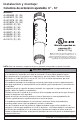


3 of 9
ISSUED: 10-10-09 SHEET NO: 154-9013-3 08-21-12
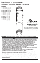
Peerless Industries, Inc.
2300 White Oak Circle
Aurora, Il 60502
www.peerlessmounts.com
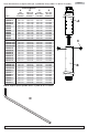
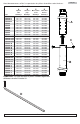
Insert extension pipe (B) into adjuster tube (A)
and secure with one screw (C). Adjust extension
pipe to locate screw (C) into desired hook slot as
shown in fi gure 2.1.
Insert second screw (C) through hole opposite
of hook slot as shown in fi gure 2.2. Tighten both
screws (C) using allen wrench (D).
2
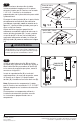
• Adjuster tube (A) must be fully threaded (six
or seven full turns) onto threaded fi tting in
ceiling plate and then locked with
M5 x 10 mm screw.
WARNING
Note: Adjustable extension column should only
be connected to UL Listed Peerless ceiling plates
with 1 1/2"-11.5 NPT threading. See instruc-
tions provided with ceiling plate for additional
assistance.
Thread adjuster tube (A) into bottom of threaded
fi tting on ceiling plate (sold separately) as shown
in fi gure 1.1. Tighten adjuster tube so thread is
securely engaged.
1
© 2011, Peerless Industries, Inc. All rights reserved.
All other brand and product names are trademarks or registered
trademarks of their respective owners.
ceiling plate
(sold separately)
HOOK
SLOTS
C
C
A
B
A
M5 x 10mm screw
(not included)
fi g 1.1
fi g 1.2
fi g 2.1
fi g 2.2
Note: Only UL Listed Peerless components with
1 1/2"-11.5 NPT threading should be connected
to the adjustable extension column.
To connect additional component to adjustable
extension column see instructions provided with
your component.
1 1/2"-11.5 NPT
threading
Align one small hole in the threaded fi tting of
ceiling plate with slot of adjuster tube (A). Insert
and tighten one M5 x 10 mm screw (not included)
through the hole of threaded fi tting and slot of
adjuster tube (A) as shown in fi gure 1.2.